There's an old African proverb that says "If you want to go quickly, go alone. If you want to go far, go together." We have to go far — quickly. And that means we have to quickly find a way to change the world's consciousness about exactly what we're facing, and why we have to work to solve it.
~ Al Gore (winner of the Nobel Peace Prize of 2007)
Friday, March 18, 2011
Insitu Uranium Mining
Insitu Uranium Leach Mining
In Situ Leach Mining
What is ISL and How long has it been used?
ISL Uranium Deposit Characteristics
ISL Wellfield -an overview
Uranium Recovery
ISL in Australia
Environment & Health
sources
In Situ Leach Mining
Most uranium mining in USA is now by in situ leach (ISL) methods. In USA it is seen as the most cost effective and environmentally acceptable method of mining. There are two proposals well advanced for ISL mining of uranium in Australia.
Conventional mining involves removing rock from the ground, breaking it up and treating it to remove the minerals being sought.
What is ISL and How long has it been used? In situ leaching (ISL), also known as solution mining, involves leaving the ore where it is in the ground, and using liquids which are pumped through it to recover the minerals out of the ore by leaching. Consequently there is little surface disturbance and no tailings or waste rock generated. However, the orebody needs to be permeable to the liquids used, and located so that they do not contaminate ground water away from the orebody.
ISL mining was first tried on an experimental basis in Wyoming during the early 1960s. The first commercial mine began operating in 1974. Today about a dozen projects are licensed to operate in the USA, (in Wyoming, Nebraska and Texas) and most of the operating mines are less than 10 years old. Most are small, by Australian standards but they supply some 85% of the US uranium production. About 13% of world uranium production is by ISL (including all Kazakhstan and Uzbekistan output).
ISL can also be applied to other minerals such as copper and gold.
ISL Uranium Deposit Characteristics Uranium deposits suitable for ISL occur in permeable sand or sandstones, confined above and below by impermeable strata and below the water table. They may either be flat, or "roll front",- in cross section, C-shaped deposits within a permeable sedimentary layer.
They were formed by the lateral movement of groundwater bearing oxidised uranium minerals through the aquifer, with precipitation of the minerals occurring when the oxygen content decreased, along extensive oxidation-reduction interfaces. The uranium minerals are usually uraninite (oxide) or coffinite (silicate) coatings on individual sand grains. The ISL process essentially reverses this ore genesis, in a much shorter time frame.
Techniques for ISL have evolved to the point where it is a controllable, safe, and environmentally benign method of mining which can operate under strict environmental controls and which often has cost advantages.
ISL Wellfield -an overview Wells are cased to ensure that liquors only flow to and from the ore zone. Submersible electric pumps draw from near the bottom of the production wells.
A wellfield design is typically a grid with alternating production and injection wells. The spacing between them usually ranges from 15 to 30 metres. A series of monitor wells are situated around the whole wellfield to ensure that contaminated water does not move outside the mining area.
Oxygen is injected into the leach liquors as they are returned to the injection wells and drawn into the ore zone to oxidise the uranium minerals. They are then removed as the liquors are pumped out.
While uranium production in Australia uses acid leaching of the crushed ore, ISL overseas normally uses alkaline leaching agents such as a combination of sodium bicarbonate and carbon dioxide. At Honeymoon in SA, the process will be acid leaching with weak sulfuric acid plus oxygen. The leaching solution is at a pH of 2.8 - 2.0, about the same as vinegar.
In USA the production life of an individual ISL wellfield is usually less than 3 years, typically 6-10 months. Most of the uranium is recovered during the first 6 months of the wellfield's operation. The most successful operations have achieved a total overall recovery of about 80% of the ore. Over time, production flows decrease as clay and silt become trapped in the permeable sediments. These can be dislodged to some extent by using higher-pressure injection or by reversing the flow between injection and production wells.
Uranium Recovery The pregnant solution from the production wells is pumped to the treatment plant where the uranium is removed from it in an ion exchange system; or by solvent extraction. The uranium is then stripped from the ion exchange resin, and precipitated chemically.
Most of the solution is returned to the injection wells, but a little is bled off and treated as wastewater. It contains various dissolved minerals such as radium, arsenic and iron. Barium chloride is added to precipitate the radium. This bleed of process solution ensures that there is a steady flow into the wellfield from the surrounding aquifer, rather than having any leach liquor move in the other direction. Before the process solution is reinjected, it is oxygenated and if necessary recharged with sodium bicarbonate or acid.
ISL in Australia Two projects are currently proposed for ISL mining operations in Australia; Honeymoon and Beverley, both in the Lake Frome area of South Australia between Broken Hill and the northern Flinders Ranges.
At Honeymoon the uranium deposit occurs in porous sandstone at a depth of 100 to 120 metres and extending over about 24 hectares of a buried riverbed (palaeochannel).
Honeymoon was discovered in 1972, about 75 kilometres north west of Broken Hill. Early in 1997 Sedimentary Holdings NL reached agreement with MIM Holdings Ltd to acquire the Honeymoon and two adjacent uranium deposits next to its own Chatfield (East Kalkaroo) deposits.
This brings together uranium resources of about 6800 tonnes U3O8 averaging 0.15% and amenable to ISL. The purchase was funded by Southern Cross Resources Inc. of Toronto which raised funds in Canada for the development of the SA uranium properties. Sedimentary Resources (an Australian company) holds 35% of Southern Cross.
Plans had been developed in the 1970s to extract the uranium oxide by ISL, and some $12 million was spent in preparation then. Draft and Final Environmental Impact Statements were produced, and both South Australian and Commonwealth environmental approval was subsequently obtained in 1981 for production to 450 t/yr. Field tests of the in situ leaching process were carried out and a $3.5 million, 110 t/yr pilot plant was built and remains on site, but the project was abandoned in 1983*.
Southern Cross now plans to bring Honeymoon and the associated deposits into production in 1998, building up to 450 tonnes per year by 2000.
The Beverley deposit, 520 kilometres north of Adelaide is northwest of Honeymoon and geologically similar to it. Plans to mine it by ISL were abandoned in 1983 when the South Australian Government refused to grant permission for development to proceed*. The deposit was sold to Heathgate Resources Pty Ltd, an affiliate of General Atomics of USA, in 1990.
Three ore lenses lie at a depth of 110-140 metres, over some 4 km. Their 6 million tonnes of 0.27% ore contains 16 200 tonnes of uranium oxide. An estimated 11 500 tonnes of this was considered recoverable by ISL at 900 tonnes per year, making it the largest Australian deposit of its kind.
Hydrogeological tests and operation of a continuous field leach trial are being undertaken in 1997-98, along with preparation of a new Environmental Impact Statement. Heathgate Resources is working towards commencing production before 2000.
Environment & Health At established operations overseas, after ISL mining is completed, the quality of the remaining groundwater must be restored to a baseline standard determined before the start of the operation, so that any prior use can be resumed. Contaminated water drawn from the aquifer is either evaporated or treated before reinjection.
In contrast to the main US operations, the water quality at the Australian sites is very low to start with, and it is quite unusable. At Beverley the groundwater in the orebody is very saline and orders of magnitude too high in radionuclides for any permitted use. At Honeymoon the water is similarly very saline, and high in sulfates and radium. When acid leaching is discontinued, the water quality reverts to its original condition.
Upon decommissioning, wells are sealed or capped, process facilities removed, any evaporation pond revegetated, and the land can readily revert to its previous uses.
The usual radiation safeguards are applied at an ISL mining operation, despite the fact that most of the orebody's radioactivity remains well underground and there is hence no increase in radon release and no ore dust. Employees are monitored for alpha radiation contamination and personal dosimeters are worn to measure exposure to gamma radiation. Routine monitoring of air, dust and surface contamination are undertaken.
- due to the ALP "3 mines" policy
Information Administration, Uranium Industry Annual. Uranium Institute, 1996, Global Nuclear Fuel Market,supply & demand 1995-2015.
Solar Energy
http://earthsci.org/mineral/energy/solar/solar.html
Photovoltaic Systems
Movement of Light
Solar Cell Materials
Turning Sunlight into Energy
From Cells to Arrays
Cells to Arrays - a closer look
PV Cells with Battery Storage
How does a cell produce electricity?
Glossary of PV Terms
Photovoltaic (or PV) systems convert light energy into electricity. The term "photo" is a stem from the Greek "phos," which means "light." "Volt"is named for Alessandro Volta (1745-1827), a pioneer in the study of electricity. "Photo-voltaics," then, could literally mean "light-electricity. Most commonly known as "solar cells," PV systems are already animportant part of our lives. The simplest systems power many of the small calculators and wrist watches we use every day. More complicated systems provide electricity for pumping water, powering communications equipment, and even lighting our homes and running our appliances. In asurprising number of cases, PV power is the cheapest form of electricity for performing these tasks.
Here, we describe the PV effect that allows various materials to produce electricity from sunlight; show how PV cells, modules, and arrays are made; explain why PV is the most logical power choice in many different cases; and provide real examples of how this science is improving the lives of people all over the world!

Movement of Light
The movement of light from one location to another can best be describedas though it were a wave, and different types of radiation are characterizedby their individual wavelengths (a wavelength is the distance from the peakof one wave to the peak of the next). These wavelengths indicate radiationwith different amounts of energy; the longer the wavelength, the less the energy. Red light, then, has a longer wavelength and thus has less energythan violet light.
Each second, the sun releases an enormous amount of radiant energy intothe solar system. The Earth receives a tiny fraction of this energy; still, anaverage of 1367 watts (W) reaches each square meter (m2) of the outeredge of the Earth's atmosphere. The atmosphere absorbs and reflects some of this radiation, including most X-rays and ultraviolet rays. Still, the amount of sunshine energy that hits the surface of the Earth every minute is greater than the total amount of energy that the world's human population consumes.
The most important parts of a solar cell are the semiconductor layers, because this is where the electron current is created. There are a number of different materials suitable for making these semiconducting layers, and each has benefits and drawbacks. Unfortunately, there is no one ideal material for all types of cells and applications. In addition to the semiconducting materials, solar cells consist of a top metallic grid or other electrical contact to collect electrons from the semiconductor and transfer them to the external load, and a back contactlayer to complete the electrical circuit. Then, on top of the complete cell is typically a glass cover or other type of transparent encapsulant to seal the cell and keep weather out, and an anti reflective coating to keep the cell from reflecting the light back away from the cell.

A typical solar cell consists of a cover glass or other encapsulant, an anti-reflective layer, a front contact to allow the electrons to enter a circuit and a back contact to
allow them to complete thecircuit, and the semiconductor layers where the electrons begin and complete their voyages.
Here are some substances commonly used in solar cells:
Silicon
Silicon is still the most popular solar cell material for commercial applications because it is so readily abundant (it is actually the second most abundant element in the Earth's crust second only to oxygen!). However, to be useful in solar cells, it must be refined to 99.9999% purity.
In single-crystal silicon, the molecular structure of the material is uniform because the entire structure is grown from the same or a "single" crystal. This uniformity is ideal for efficiently transferring electrons through the material. To make an effective PV cell, silicon is "doped" to make it n-type and p-type. Semicrystalline silicon, on the other hand, consists of several smaller crystals or "grains," which introduce "boundaries." These boundaries impede the flow of electrons and encourage them to recombine with holes and thereby reduce the power output of the cell. However, semicrystalline silicon is much cheaper to produce than single-crystalline silicon, so researchers are working on other ways of minimizing the effects of grain boundaries.
Gallium Arsenide
Gallium arsenide (GaAs) is a compound semiconductor: a mixture of two elements, gallium (Ga) and arsenic (As). Gallium is a byproduct of the smelting of other metals, notably aluminum and zinc, and it is rarer than gold. Arsenic is not rare, but it is poisonous. Gallium arsenide's use in solar cells has been developing synergistically with its use in light-emitting diodes, lasers, and other opto-electronic devices.
GaAs is especially suitable for use in multijunction and high-efficiency solar cells for several reasons:
1. The GaAs band gap is 1.43 eV, nearly ideal for single-junction solar cells.
2. GaAs has an absorbtivity so high it requires a cell only a few microns thick to absorb sunlight. (Crystalline silicon requires a layer 100 microns or more in thickness.)
3. Unlike silicon cells, GaAs cells are relatively insensitive to heat. (Cell temperatures can often be quite high, especially in concentrator applications.)
4. Alloys made from GaAs using aluminum, phosphorus, antimony, or indium have characteristics complementary to those of gallium arsenide, allowing great flexibility in cell design.
5. GaAs is very resistant to radiation damage. This, along with its high efficiency, makes GaAs very desirable for space applications.
One of the greatest advantages of gallium arsenide and its alloys as PV cell materials is the wide range of design options possible. A cell with a GaAs base can have several layers of slightly different compositions that allow a cell designer to precisely control the generation and collection of electrons and holes. (To accomplish the same thing, silicon cells have been limited to variations in the level of doping.) This degree of control allows cell designers to push efficiencies closer and closer to theoretical levels. For example, one of the most common GaAs cell structures uses a very thin window layer of aluminum gallium arsenide. This thin layer allows electrons and holes to be created close to the electric field at the junction.
Polycrystalline Thin Films
One of the scientific discoveries of the computer semiconductor industry that has shown great potential for the PV industry is thin film technology. Polycrystalline thin film devices require very little semiconductor material and have the added advantage of being easy to manufacture. Rather than growing, slicing, and treating a crystalline ingot (required for single-crystal silicon), we sequentially deposit thin layers of the required materials.
Several different deposition techniques are available, and all of them are potentially cheaper than the ingot growth techniques required for crystalline silicon. Best of all, these deposition processes can be scaled uneasily so that the same technique used to make a 2-inch x 2-inch laboratory cell can be used to make a 2-foot x 5-foot module (in a sense, a huge cell!). Like amorphous silicon, the layers can be deposited on various low-cost substrates (actually "superstrates," see Transparent Conductors)
like glass or plastic in virtually any shape -- even flexible plastic sheets.
Single-crystal cells have to be individually interconnected into a module, but thin film devices can be made monolithically (as a single unit). Layer upon layer is deposited sequentially on a glass superstrate, from the antireflection coating and conducting oxide, to the semiconductor materialand the back electrical contacts.
Polycrystalline Thin Films:
Cell Structure
Unlike most single-crystal cells, the typical thin film device does not use a metal grid for the top electrical contact. Instead, it uses a thin layer of a transparent conducting oxide (such as tin oxide). These oxides are highly transparent and conduct electricity very well. A separate antireflection coating may be used to top off the device, or the transparent conducting oxide may serve this function as well.
Polycrystalline thin film cells comprise many tiny crystalline grains of semiconductor materials. The materials used in polycrystalline thin-film cells have properties that are different from those of silicon, so it has proven to be better to create the electric field with an interface between two different semiconductor materials. This type of interface is called a heterojunction ("hetero" because it is formed from two different materials,
in comparison to the "homojunction" formed by two doped layers of the same material, such as the one in silicon solar cells).
Turning Sunlight into Energy
About Conversion Efficiencies
The conversion efficiency of a PV cell is the proportion of sunlight energythat the cell converts to electrical energy. This is very important whendiscussing PV devices, because improving this efficiency is vital to makingPV energy competitive with more traditional sources of energy (e.g., fossilfuels). Naturally, if one efficient solar panel can provide as much energy as two less efficient panels, then the cost of that energy (not to mention the space required) will be reduced. For comparison, the earliest PV devicesconverted about 1%-2% of sunlight energy into electric energy. Today'sPV devices convert 7%-17% of light energy into electric energy.Of course, the other side of the equation is the money it costs to manufacture the PV devices. This has been improved over the years aswell. In fact, today's PV systems produce electricity at a fraction of thecost of early PV systems.

AC and DC Current
PV modules, because of their electrical properties, produce direct ratherthan alternating current (ac). Direct current (dc) is electric current thatflows in a single direction. Many simple devices, such as those that run onbatteries, use direct current. Alternating current, in contrast, is electriccurrent that reverses its flow direction at regular intervals. This is the typeof electricity provided by utilities and is required to run most modern appliances and electronic devices.
In the simplest systems, dc current produced by PV modules is useddirectly. In applications where ac current is necessary, an inverter can beadded to the system to convert the dc current to ac current.
Turning Sunlight Into Electricity
Light and the Sun
The sun's energy is vital to life on Earth. It determines the Earth's surfacetemperature and supplies virtually all the energy that drives natural globalsystems and cycles. Although some other stars are enormous sources ofenergy in the form of X-rays and radio signals, our sun releases 95% of itsenergy as visible light. Yet, visible light represents only a fraction of thetotal radiation spectrum; infrared and ultraviolet rays are also significantparts of the solar spectrum.
frequency and the greater the
energy (expressed in eV, or electron volts).
Each portion of the solar spectrum is associated with a different level ofenergy. Within the visible portion of the spectrum, for example, red light isat the low-energy end and violet light is at the high-energy end (having halfagain as much energy as red light). In the invisible portions of thespectrum, photons in the ultraviolet region, which cause the skin to tan,have more energy than those in the visible region. Likewise, photons in theinfrared region, which we feel as heat, have less energy than the photonsin the visible region.
The "photovoltaic effect" is the basic physical process through which a PVcell converts sunlight into electricity. Sunlight is composed of photons, orparticles of solar energy. These photons contain various amounts ofenergy corresponding to the different wavelengths of the solar spectrum (see "Light and the Sun" for more about that). When photons strike a PVcell, they may be reflected or absorbed, or they may pass right through.
Only the absorbed photons generate electricity. When this happens, theenergy of the photon is transferred to an electron in an atom of the cell(which is actually a semiconductor). With its newfound energy, the electron is able to escape from its normal position associated with thatatom to become part of the current in an electrical circuit. By leaving thisposition, the electron causes a "hole" to form. Special electrical propertiesof the PV cell-a built-in electric field provide the voltage needed to drive
the current through an external load (such as a light bulb).
p-Types, n-Types, and the Electric Field
To induce the electric field within a PV cell, two separate semiconductorsare sandwiched together. The "p" and "n" types of semiconductorscorrespond to "positive" and "negative" because of their abundance ofholes or electrons (the extra electrons make an "n" type because an electron actually has a negative charge).
Although both materials are electrically neutral, n-type silicon has excess electrons and p-type silicon has excess holes. Sandwiching these togethercreates a p/n junction at their interface, thereby creating an electric field. When the p-type and n-type semiconductors are sandwiched together, theexcess electrons in the n-type material flow to the p-type, and the holes
thereby vacated during this process flow to the n-type. (The concept of a hole moving is somewhat like looking at a bubble in a liquid. Although it's the liquid that is actually moving, it'seasier to describe the motion of thebubble as it moves in the opposite direction.) Through this electron andhole flow, the two semiconductors act as a battery, creating an electricfield at the surface where they meet (known as the "junction"). It's this
field that causes the electrons to jump from the semiconductor out toward the surface and make them available for the electrical circuit. At this sametime, the holes move in the opposite direction, toward the positive surface, where they await incoming electrons.

From Cells to Arrays
The PV cell is the basic unit in a PV system. An individual PV cell typicallyproduces between 1 and 2 watts, hardly enough power for the greatmajority of applications. But we can increase the power by connectingcells together to form larger units called modules. Modules, in turn, can beconnected to form even larger units known as arrays, which can be interconnected for more power, and so on. In this way, we can build a PVsystem to meet almost any power need, no matter how small or great.
Modules or arrays, by themselves, do not constitute a PV system. We must also have structures on which to put them and point them toward thesun, and components that take the direct current (dc) electricity producedby the modules or arrays and condition the electricity so it can be used inthe specific application. These structures and components are referred toas the balance of system (BOS).

When sunlight strikes a solar cell, only certain bands (or wavelengths)of light will cause electrons to move within the semiconductor, therebyproducing electric current. The energy "band gap" of thesemiconductor determines the ideal portion of the light spectrum that will create this effect. To allow it all to happen, the semiconductorlayers must be constructed so as to produce an electric fieldThe wavelengths of light above the cell's band gap (left) carry more energy. Some of this energy is absorbed to free electrons in the cell,and some of it is absorbed as heat. Light energy below the cell's band gap
(right) passes right through the field without affecting electron movement. Overall, only abut 55% of the sun's light energycan be converted into electricity.

So, the typical solar cell receives the entire solar spectrum. But onlythe light energy above the cell's energy gap
will cause electrons to move and become part of an electric circuit.
Cells to Arrays
The solar cell is the basic building block of a PV system. Individual cells can vary in size from about 1 cm (1/2 in.) to about 10 cm (4 in.) across. However, one cell only produces 1-2 W, which isn't enough power for most applications

(Photo: Siemens Solar Industries)
A module typically consists of several solar cells, although thin-film materials like amorphous silicon and cadmium
telluride can be made directly into modules, effectively bypassing the solar cell. These two silicon modules are rated at approximately 50 W each and provide power for a street light using 12 V battery storage.

Modules such as these can also be connected into arrays for more power.
(Photo: W. Gretz, NREL)
Arrays are the large power producers and consist of several modules. They can be used to provide up to several megawatts of electric power.
The basic photovoltaic cell typically produces only a small amount of power. To produce more power, cells can be interconnected to form modules, which can in turn be connected into arrays to produce yet more power. Because of this modularity, PV systems may be designed to meet any electrical requirement, no matter how large or how small.
PV Cells with Battery Storage
PV systems with batteries operate by connecting the PV modules to abattery, and the battery, in turn, to the load. During daylight hours, the PVmodules charge the battery. The battery supplies power to the loadwhenever needed. A simple electrical device called a charge controllerkeeps the batteries charged properly and helps prolong their life by protecting them from overcharging or from being completely drained. Batteries make PV systems useful in more situations, but also require somemaintenance. The batteries used in PV systems are often similar to carbatteries, but are built somewhat differently to allow more of their storedenergy to be used each day. (They are said to be "deep cycling," like thebatteries used on golf carts.) Batteries designed for PV projects pose thesame risks and demand the same caution in handling and storage as automotive batteries. The fluid in unsealed batteries should be checkedperiodically, and batteries should be protected from extremely cold weather.
A solar generating system with batteries supplies electricity when it isneeded. How much electricity can be used after sunset or on cloudy daysis determined by the output of the PV modules and the nature of thebattery bank. Including more modules and batteries increases system cost, so energy usage is carefully studied to determine optimum system size. Awell designed system balances cost and convenience to meet the user'sneeds, and can be expanded if those needs change.
How does a cell produce electricity?
A typical solar cell is made from a substance called silicon. Silicon is known as a semiconductor. A semiconductor is neither a good insulator nor a good insulator; it falls somewhere in between. A solar cell is constructed with silicon that has been altered to form two different types of semiconductor material. These two different types of silicon are then joined in such a way as to form a junction.
Due to the different types of semiconductor material that make up this junction, a permanent electric field is forced to appear in this region. When a photon from a light source such as the sun strikes the cell, it causes an electron in the semiconductor material to jump to a higher orbit and jump from atom to atom. The permanent electric field forces the electron to move only in a particular direction, out of the cell and through a circuit such as a light bulb, a motor or battery etc. and then back to the other side of the junction thus performing work.
By connecting cells together to form a solar panel we can do even more work. The typical individual silicon solar cell has the potential of generating about half a volt, but by wiring them in series or end to end you can increase the voltage. In other words, 36 individual cell will produce about 18 volts. The size of the individual cell is what determines the amount of current of amps that a solar panel can produce.
Glossary of PV Terms
This brief glossary is offered as a basic guideline. Click on any term to receive the definition, then click on the term again to return here.
AC
Ampere
Ampere Hour
Ampere Hour Meter
Angle Of Incidence
Array
Balance Of System
Battery
Battery Capacity
Battery Cell
Battery Available Capacity
Battery Energy Capacity
Battery Cycle Life
Battery Life
Blocking Diode
Cathodic Protection
Cell (Battery)
Cell (Solar)
Charge Rate
Charge Controller
Concentrator
DC
Depth Of Discharge
Diffuse Insolation
Direct Insolation
Efficiency
Electrolyte
Electric Current
Electricity Energy
Electrons
Equalization
Equalizing Charge
Float Service
Full Sun
Gassing
Grid
Grid Lines
Hermetic Seal
Hybrid System
Incident Light
Insolation
Inverter
Kilowatt-Hour (Comparison Of Fuel Equivalents)
Load
Maximum Power
Module
Open Circuit Voltage
Panel
Parallel Connection
Peak Power Point
Peak Watts
Photon
Photovoltaic Cell
Photovoltaic Effect
Photovoltaic System
Power Conditioner
Power Factor
Regulator
Renewable Energy
Semiconductor
Series Connection
Silicon
Single-Crystal Structure
Solar Cell
Solar Panel
Stand-Alone System
Storage Battery
Sulfation
Telemetry Device
Tilt Angle
Tracking Array
Voltage
Watt
AC: Alternating Current. Direction of current reverses periodically, usually many times per second. Electricity transmission networks use AC because voltage can be controlled with relative ease.
Ampere (amp): A unit of electrical current or rate of flow of electrons. One volt across one ohm of resistance causes a current flow of one ampere. One ampere is equal to 6.235 x 10¹⁸ electrons per second passing a given point in a circuit.
Ampere hour: (amp hr. Or ah), a measure of current overtime, used to measure battery capacity.
Ampere hour meter: An instrument that monitors current
with time. The indication is the product of current (in amperes) and time (in hours).
Angle of Incidence: The angle between the direct solar beam and the normal (90 degrees) to the active surface (degrees).
Array: Any number of photovoltaic modules connected together electrically to provide a single electrical output. An array is a mechanically integrated assembly of modules or panels together with support structure (including foundation and other components, as required) to form a free- standing field installed unit that produces DC power.
Balance of systems (bos): Parts or components of a photovoltaic system other than the photovoltaic array.
Battery: Two or more electrochemical cells enclosed in
a container and electrically interconnected in an appropriate series/parallel arrangement to provide the required operating voltage and current levels. Under common usage, the term battery also applies to a single cell if it constitutes the entire
electrochemical storage system.
Battery capacity: The maximum total electrical charge,expressed in ampere-hours (ah), that a battery can deliver to a load under a specific set of conditions.
Battery cell: The simplest operating unit in a storage
battery. It consists of one or more positive electrodes or plates, an electrolyte that permits ionic conduction, one or more negative electrodes or plates, separators between plates of opposite polarity, and a container for all the above.
Battery available capacity: The total maximum charge, expressed in ampere-hours, that can be withdrawn from a cell or battery under a specific set of operating conditions including discharge rate, temperature, initial state of charge, age, and cutoff voltage.
Battery energy capacity: the total energy available, expressed in watt-hours (kilowatt-hours), that can be withdrawn from a fully-charged cell or battery. The energy capacity of a given cell varies with temperature, rate, age, and cutoff voltage.
This term is more common to system designers than it is to the battery industry where capacity usually refers to ampere-hours..
Battery cycle life: The number of cycles, to a specified depth of discharge, that a cell or battery can undergo before failing to meet its specified capacity or efficiency performance criteria..
Battery life: The period during which a cell or battery
is capable of operating above a specified capacity or efficiency performance level. For example, with lead-acid batteries, end-of- life is generally taken as the point in time when a fully charged cell can deliver only 80% of its rated capacity. Beyond this state of aging, deterioration and loss of capacity begins to accelerate rapidly. Life may be measured in cycles and/or years, depending on the type of service for which the cell or battery is intended.
Blocking diode: A semiconductor connected in series
with a solar cell or cells and a storage battery to keep the battery from discharging through the cell when there is no output, or low output, from the solar cell. It can be thought of as a one-way valve that allows electrons to flow forwards, but not backwards.
Cathodic protection: Systems that protect underground
metal from corrosion by running small electrical currents along the metal. Most often used to protect wellheads, oil, gas, and water pipelines.
Cell (battery): A single unit of an electrochemical device capable of producing direct voltage by converting chemical energy into electrical energy. A battery usually consists of several cells electrically connected together to produce higher voltages. (sometimes the terms cell and battery are used interchangeably).
Cell (solar): The smallest, basic photovoltaic device that generates electricity when exposed to light.
Charge rate: The current applied to a cell or battery to restore its available capacity. This rate is commonly normalized by a charge control device with respect to the rated capacity of the cell or battery.
Charge controller: a component of photovoltaic system that controls the flow of current to and from the battery to protect the batteries from over-charge and over-discharge. The charge controller may also indicate the system operational status.
Concentrator: a photovoltaic module which includes optical components, such as lenses, to direct and concentrate sunlight onto a solar cell of smaller area. Most concentrator arrays must directly face or track the sun.
DC: Direct Current. A one way flow of electric current. Typical sources of direct currents are electric cells, rectified power units and direct current generators. This is the current flow produced by a solar cell system. To be used for typical 120 volt or 220 volt household appliances, it must be converted to AC.
Depth of Discharge (dod): The ampere-hours removed from a fully charged cell or battery, expressed as a percentage of rated capacity. For example, the removal of 25 ampere- hours from a fully charged 100 ampere-hours rated cell results in a 25% depth of discharge. Under certain conditions, such as discharge rates lower than that used to rate the cell, depth of discharge can exceed 100%.
Diffuse insolation: The radiant energy from the sky incident upon unit surface area during a specified time period (same units as for direct insolation).
Direct insolation: The radiant energy from the sun (and a small area of sky surrounding it, defined by the acceptance angle of the pyrheliometer) incident upon unit surface area during a specified time period. (mj/m2 per hour, day, week, month or year, as the case may be).
Efficiency: The ratio of power output of a photovoltaic cell to the incident power from the sun or simulated sun sources under specified standard insolation conditions.
Electrolyte: The fluid used in batteries as the transport medium for positively and negatively charged ions.
Electric current: The rate at which electricity flows
through an electrical conductor, usually measured in amperes (amps).
Electricity energy: Resulting from the flow of charge particles, such as electrons ions.
Electrons: A negatively charged particle. The movement of electrons in an electrical conductor constitutes an electric current.
Equalization: The process of restoring all cells in a battery to an equal state-of-charge. For lead-acid batteries, this is a charging process designed to bring all cells to 100% state- charge. Some battery types may require a complete discharge as a part of the equalization process.
Equalizing charge: A continuation of normal battery charging, at a voltage level slightly higher than the normal end-of-charge voltage, in order to provide cell equalization within a battery.
Float service: A battery operation in which the battery is normally connected to an external current source; for instance, a battery charger which supplies the battery load under normal conditions, while also providing enough energy input to the battery to make up for its internal quiescent losses, thus keeping the battery always up to full power and ready for service.
Full sun: The full sun condition is the amount of power density received at the surface of the earth at noon on a clear day - about 100 mw/cm2. Lower levels of sunlight are often expressed as 0.5 sun or 0.1 sun. A figure of 0.5 sun means that the power density of the sunlight is one-half of that of a full sun.
Gassing: The evolution of gas from one or more of the electrodes in the cells of a battery. Gassing commonly results from local action self-discharge) or from the electrolysis of water in the electrolyte during charging.
Grid: Transmission line network used to distribute electric power.
Grid lines: Metallic contacts fused to the surface of the solar cell to provide a low resistance path for electrons to flow out to the cell interconnect wires.
Hermetic seal: Being impervious to external influences. Typically associated with the sealing of a package so that oxygen, moisture, and other outside environments cannot enter the package.
Hybrid system: a power system consisting of two or more power generating subsystems (e.g., The combination of a wind turbine or diesel generator and a photovoltaic system. The SES Photogenset® is an example of such a system.
Incident light: The incident light is the amount of light reaching an object.
Insolation: The amount of sunlight reaching an area. Usually expressed in milliwatts per square centimeter, or langleys.
Inverter: a device that converts electricity from DC to AC.
Kilowatt-hour unit of energy used to perform work (energy and work are equivalent in units, energy being the potential value and work the achieved value)
Fuel equivalents:
one barrel of crude contains roughly 1700 kwh
one ton of coal contains roughly 7500 kwh
one gallon of gasoline contains roughly 37 kwh
one cubic foot of natural gas contains 0.3 kwh
one ton of uranium ore contains 164 million kwh 1.34
horsepower-hours.
Thermal unit:
one kwh = 3400 btu. Can be compared to 860 calories
(food value)
Example:
The 'average Australian home uses about 20 kwh of
electricity per day. Heating 12Litres of water from 30 degrees to the boiling point requires 1 kwh. A 200 watt photovoltaic array of six, 50 watt solar modules, will generate 1 kwh in an "average" day (annualized average equivalent of 5 hours peak sunlight per day).
Load: Refers to equipment that is powered by electricity. Usually expressed in terms of amperes or watts. In an electrical circuit, any device or appliance that uses power (such as a light bulb or water pump).
Maximum power: The power at the point on the current-voltage characteristic where the product of current and voltage is a maximum (measured in watts).
Module: The smallest non divisible, self-contained and environmentally protected physical structure housing interconnected photovoltaic cells and providing a single DC electrical output.
Open circuit voltage (ocv): Voltage produced by a
photovoltaic cell with noload applied when the cell is exposed to standardinsolation conditions, measured with a voltmeter.
Panel: A collection of one or more modules fastened together into a single unit, often factory pre- assembled and wired, forming a field-installable unit.
Parallel connection: A wiring configuration used to increase current (amperage). Parallel wiring is positive to positive (+ to +) and negative to negative (- to -). Opposite of a series connection.
Peak power point: Operating point of the i-v (current-voltage) curve for a photovoltaic cell or module where the product of the current value times the voltage value is a maximum.
Peak watts: The measurement of electricity produced by a solar generator at noon on a sunny day, under predetermined standard conditions.
Photon: The actual (physical) particle unit of light,
as the electron is of electric charge and the atom and molecule are of matter. Light has both wave properties and particle properties. Violet light has relatively short wavelength and higher energy in its photons; red light has longer wavelength, lower-energyphotons. The wavelength and/or energy spectrum of the sun extends in both directions beyond the visible range of light, of course, and the silicon module solar cell can capture some energy both of these invisible zones. Photons not captured by the cell are either reflected or converted to heat in the solar array.
Photovoltaic cell: A device composed of specially prepared semiconductor material or material combinations exhibiting the ability to convert incident solar energy directly into electrical energy.
Photovoltaic effect: The phenomenon that occurs when photons, the "particles" in a beam of light, knock electrons loose from the atoms they strike. When this property of light is combined with the properties of semiconductors, electrons flow in one direction across a junction, setting up a voltage. With the addition of circuitry, current will flow and electric power will be available.
Photovoltaic system: An installed aggregate of solar
arrays generating power for a given application. A system may include the following sub-systems:
a. support foundation
b. power conditioning and control equipment
c. storage
d. active thermal control
e. land security systems and buildings
f. conduit/wiring
g. instrumentation
Power conditioner: The electrical equipment used to convert power from a photovoltaic array into a form suitable for subsequent use. Loosely, a collective term for inverter, transformer, voltage regulator and other power controls.
Power factor: The ratio of real power (watts) to
apparent power (volt amps) in an AC circuit. Displacement power factor is the ratio of fundamental watts to fundamental RMS volts times RMS amps, excluding the effects of all harmonic exponents; it could be called fundamental power factor.
Regulator: Prevents overcharging of batteries by controlling charge cycle - usually adjustable to conform to specific battery needs.
Renewable energy: Flows of energy that are regenerative or virtually inexhaustible. Most commonly includes solar electric and thermal), biomass, geothermal, wind, tidal, wave, and hydro power sources.
Semiconductor: A material such as silicon, which has a
crystalline structure that will allow current to flow under certain conditions. Semiconductors are usually less conductive than metals but not an insulator like rubber.
Series connection: A wiring configuration used to increase voltage. Series wiring is positive to negative (+ to -) or negative to positive (- to +). Opposite of parallel connection.
Silicon: A non-metallic element, that when specially treated, is sensitive to light and capable of transforming light into electricity. Silicon is the basic material of most beach sand, and is the raw material used to manufacture most photovoltaic cells.
Single-crystal structure: A material having a crystalline structure such that a repeatable or periodic molecular pattern exists in all three dimensions.
Solar cell: The basic photovoltaic device which generates electricity when exposed to sunlight.
Solar panel: A collection of solar modules connected in
series, in parallel, or in series- parallel combination to provide greater voltage, current, or power than can be furnished by a single solar module. Solar panels can be provided to furnish any desired voltage, current, or power. They are made up as a complete assembly. Larger collections of solar panels are usually called
solar arrays.
Stand-alone system: (sos) a system which operates independently of the utility lines. It may draw supplementary power from the utility but is not capable of providing power to the utility.
Storage battery: A device capable of transforming energy from electric to chemical form and vice versa. The reactions are almost completely reversible. During discharge, chemical energy is converted to electric energy and is consumed in an external circuit or apparatus.
Sulfation: The formation of lead sulfate crystals on the plates of a lead-acid battery. Commonly used to indicate the large crystals which form in partially discharged cells as the result of temperature cycling. These large crystals are more difficult to reduce by the charging current than are the smaller crystals that result from normal and self-discharge reactions. Sulfating can be caused by leaving the battery in a discharged state for long periods of time.
Telemetry device: Devices used to transmit or receive data in a digital form.
Tilt angle: A fixed angle measured from the horizontal to which a solar array is tilted. The tilt angle is chosen to maximize the array output. Depending upon latitude, season and time of day this angle will vary.
Tracking array: An array that is mounted on a movable structure that attempts follow the path of the sun. Some tracking arrays are single axis while others are dual.
Voltage: A measure of the force or "push" given the electrons in an electrical circuit; a measure of electrical potential. One volt produces one amp of current when acting against a resistance of one ohm.
Watt: Unit of power. Power is the rate of using energy to do work.
Additional items of interest:
mechanical: 746 watts = 1 horsepower
electrical: one watt is the power developed or
dissipated in one volt circuit
(see volt) in which a current of one ampere (6
1/4 million electrons per second) is flowing.
Watts = amps x volts.
Thermal: 1 watt = about 14.3 calories of heat
energy per minute. =3.413 BTU per hour =1 joule/sec.
Examples: typical 4" silicon cell produces about 1 watt at peak (noontime sunlight). One 1.3m fluorescent tube used 40 watts. One watt will heat announce of water from the freezing point to the boiling point in a little over 3hours. The sun delivers (at peak) about 100 watts 30sqcm of surface normally.
Solar Energy
based on web page by Ken CromptonPhotovoltaic Systems
Movement of Light
Solar Cell Materials
Turning Sunlight into Energy
From Cells to Arrays
Cells to Arrays - a closer look
PV Cells with Battery Storage
How does a cell produce electricity?
Glossary of PV Terms
Photovoltaic (or PV) systems convert light energy into electricity. The term "photo" is a stem from the Greek "phos," which means "light." "Volt"is named for Alessandro Volta (1745-1827), a pioneer in the study of electricity. "Photo-voltaics," then, could literally mean "light-electricity. Most commonly known as "solar cells," PV systems are already animportant part of our lives. The simplest systems power many of the small calculators and wrist watches we use every day. More complicated systems provide electricity for pumping water, powering communications equipment, and even lighting our homes and running our appliances. In asurprising number of cases, PV power is the cheapest form of electricity for performing these tasks.
Here, we describe the PV effect that allows various materials to produce electricity from sunlight; show how PV cells, modules, and arrays are made; explain why PV is the most logical power choice in many different cases; and provide real examples of how this science is improving the lives of people all over the world!
Movement of Light
The movement of light from one location to another can best be describedas though it were a wave, and different types of radiation are characterizedby their individual wavelengths (a wavelength is the distance from the peakof one wave to the peak of the next). These wavelengths indicate radiationwith different amounts of energy; the longer the wavelength, the less the energy. Red light, then, has a longer wavelength and thus has less energythan violet light.
Each second, the sun releases an enormous amount of radiant energy intothe solar system. The Earth receives a tiny fraction of this energy; still, anaverage of 1367 watts (W) reaches each square meter (m2) of the outeredge of the Earth's atmosphere. The atmosphere absorbs and reflects some of this radiation, including most X-rays and ultraviolet rays. Still, the amount of sunshine energy that hits the surface of the Earth every minute is greater than the total amount of energy that the world's human population consumes.
The Earth's atmosphere and cloud cover absorb, reflect, and scatter someof the solar radiation entering the atmosphere.Nonetheless, enormous amounts of direct diffuse sunshine energy reach the Earth's surfaceand
can therefore be used to produce photovoltaic electricity.
Solar Cell Materialscan therefore be used to produce photovoltaic electricity.
The most important parts of a solar cell are the semiconductor layers, because this is where the electron current is created. There are a number of different materials suitable for making these semiconducting layers, and each has benefits and drawbacks. Unfortunately, there is no one ideal material for all types of cells and applications. In addition to the semiconducting materials, solar cells consist of a top metallic grid or other electrical contact to collect electrons from the semiconductor and transfer them to the external load, and a back contactlayer to complete the electrical circuit. Then, on top of the complete cell is typically a glass cover or other type of transparent encapsulant to seal the cell and keep weather out, and an anti reflective coating to keep the cell from reflecting the light back away from the cell.
A typical solar cell consists of a cover glass or other encapsulant, an anti-reflective layer, a front contact to allow the electrons to enter a circuit and a back contact to
allow them to complete thecircuit, and the semiconductor layers where the electrons begin and complete their voyages.
Here are some substances commonly used in solar cells:
Silicon
Silicon is still the most popular solar cell material for commercial applications because it is so readily abundant (it is actually the second most abundant element in the Earth's crust second only to oxygen!). However, to be useful in solar cells, it must be refined to 99.9999% purity.
In single-crystal silicon, the molecular structure of the material is uniform because the entire structure is grown from the same or a "single" crystal. This uniformity is ideal for efficiently transferring electrons through the material. To make an effective PV cell, silicon is "doped" to make it n-type and p-type. Semicrystalline silicon, on the other hand, consists of several smaller crystals or "grains," which introduce "boundaries." These boundaries impede the flow of electrons and encourage them to recombine with holes and thereby reduce the power output of the cell. However, semicrystalline silicon is much cheaper to produce than single-crystalline silicon, so researchers are working on other ways of minimizing the effects of grain boundaries.
Gallium Arsenide
Gallium arsenide (GaAs) is a compound semiconductor: a mixture of two elements, gallium (Ga) and arsenic (As). Gallium is a byproduct of the smelting of other metals, notably aluminum and zinc, and it is rarer than gold. Arsenic is not rare, but it is poisonous. Gallium arsenide's use in solar cells has been developing synergistically with its use in light-emitting diodes, lasers, and other opto-electronic devices.
GaAs is especially suitable for use in multijunction and high-efficiency solar cells for several reasons:
1. The GaAs band gap is 1.43 eV, nearly ideal for single-junction solar cells.
2. GaAs has an absorbtivity so high it requires a cell only a few microns thick to absorb sunlight. (Crystalline silicon requires a layer 100 microns or more in thickness.)
3. Unlike silicon cells, GaAs cells are relatively insensitive to heat. (Cell temperatures can often be quite high, especially in concentrator applications.)
4. Alloys made from GaAs using aluminum, phosphorus, antimony, or indium have characteristics complementary to those of gallium arsenide, allowing great flexibility in cell design.
5. GaAs is very resistant to radiation damage. This, along with its high efficiency, makes GaAs very desirable for space applications.
One of the greatest advantages of gallium arsenide and its alloys as PV cell materials is the wide range of design options possible. A cell with a GaAs base can have several layers of slightly different compositions that allow a cell designer to precisely control the generation and collection of electrons and holes. (To accomplish the same thing, silicon cells have been limited to variations in the level of doping.) This degree of control allows cell designers to push efficiencies closer and closer to theoretical levels. For example, one of the most common GaAs cell structures uses a very thin window layer of aluminum gallium arsenide. This thin layer allows electrons and holes to be created close to the electric field at the junction.
Polycrystalline Thin Films
One of the scientific discoveries of the computer semiconductor industry that has shown great potential for the PV industry is thin film technology. Polycrystalline thin film devices require very little semiconductor material and have the added advantage of being easy to manufacture. Rather than growing, slicing, and treating a crystalline ingot (required for single-crystal silicon), we sequentially deposit thin layers of the required materials.
Several different deposition techniques are available, and all of them are potentially cheaper than the ingot growth techniques required for crystalline silicon. Best of all, these deposition processes can be scaled uneasily so that the same technique used to make a 2-inch x 2-inch laboratory cell can be used to make a 2-foot x 5-foot module (in a sense, a huge cell!). Like amorphous silicon, the layers can be deposited on various low-cost substrates (actually "superstrates," see Transparent Conductors)
like glass or plastic in virtually any shape -- even flexible plastic sheets.
Single-crystal cells have to be individually interconnected into a module, but thin film devices can be made monolithically (as a single unit). Layer upon layer is deposited sequentially on a glass superstrate, from the antireflection coating and conducting oxide, to the semiconductor materialand the back electrical contacts.
Polycrystalline Thin Films:
Cell Structure
Unlike most single-crystal cells, the typical thin film device does not use a metal grid for the top electrical contact. Instead, it uses a thin layer of a transparent conducting oxide (such as tin oxide). These oxides are highly transparent and conduct electricity very well. A separate antireflection coating may be used to top off the device, or the transparent conducting oxide may serve this function as well.
Polycrystalline thin film cells comprise many tiny crystalline grains of semiconductor materials. The materials used in polycrystalline thin-film cells have properties that are different from those of silicon, so it has proven to be better to create the electric field with an interface between two different semiconductor materials. This type of interface is called a heterojunction ("hetero" because it is formed from two different materials,
in comparison to the "homojunction" formed by two doped layers of the same material, such as the one in silicon solar cells).
Turning Sunlight into Energy
About Conversion Efficiencies
The conversion efficiency of a PV cell is the proportion of sunlight energythat the cell converts to electrical energy. This is very important whendiscussing PV devices, because improving this efficiency is vital to makingPV energy competitive with more traditional sources of energy (e.g., fossilfuels). Naturally, if one efficient solar panel can provide as much energy as two less efficient panels, then the cost of that energy (not to mention the space required) will be reduced. For comparison, the earliest PV devicesconverted about 1%-2% of sunlight energy into electric energy. Today'sPV devices convert 7%-17% of light energy into electric energy.Of course, the other side of the equation is the money it costs to manufacture the PV devices. This has been improved over the years aswell. In fact, today's PV systems produce electricity at a fraction of thecost of early PV systems.
AC and DC Current
PV modules, because of their electrical properties, produce direct ratherthan alternating current (ac). Direct current (dc) is electric current thatflows in a single direction. Many simple devices, such as those that run onbatteries, use direct current. Alternating current, in contrast, is electriccurrent that reverses its flow direction at regular intervals. This is the typeof electricity provided by utilities and is required to run most modern appliances and electronic devices.
In the simplest systems, dc current produced by PV modules is useddirectly. In applications where ac current is necessary, an inverter can beadded to the system to convert the dc current to ac current.
Turning Sunlight Into Electricity
Light and the Sun
The sun's energy is vital to life on Earth. It determines the Earth's surfacetemperature and supplies virtually all the energy that drives natural globalsystems and cycles. Although some other stars are enormous sources ofenergy in the form of X-rays and radio signals, our sun releases 95% of itsenergy as visible light. Yet, visible light represents only a fraction of thetotal radiation spectrum; infrared and ultraviolet rays are also significantparts of the solar spectrum.
frequency and the greater the
energy (expressed in eV, or electron volts).
Each portion of the solar spectrum is associated with a different level ofenergy. Within the visible portion of the spectrum, for example, red light isat the low-energy end and violet light is at the high-energy end (having halfagain as much energy as red light). In the invisible portions of thespectrum, photons in the ultraviolet region, which cause the skin to tan,have more energy than those in the visible region. Likewise, photons in theinfrared region, which we feel as heat, have less energy than the photonsin the visible region.
The "photovoltaic effect" is the basic physical process through which a PVcell converts sunlight into electricity. Sunlight is composed of photons, orparticles of solar energy. These photons contain various amounts ofenergy corresponding to the different wavelengths of the solar spectrum (see "Light and the Sun" for more about that). When photons strike a PVcell, they may be reflected or absorbed, or they may pass right through.
Only the absorbed photons generate electricity. When this happens, theenergy of the photon is transferred to an electron in an atom of the cell(which is actually a semiconductor). With its newfound energy, the electron is able to escape from its normal position associated with thatatom to become part of the current in an electrical circuit. By leaving thisposition, the electron causes a "hole" to form. Special electrical propertiesof the PV cell-a built-in electric field provide the voltage needed to drive
the current through an external load (such as a light bulb).
p-Types, n-Types, and the Electric Field
To induce the electric field within a PV cell, two separate semiconductorsare sandwiched together. The "p" and "n" types of semiconductorscorrespond to "positive" and "negative" because of their abundance ofholes or electrons (the extra electrons make an "n" type because an electron actually has a negative charge).
Although both materials are electrically neutral, n-type silicon has excess electrons and p-type silicon has excess holes. Sandwiching these togethercreates a p/n junction at their interface, thereby creating an electric field. When the p-type and n-type semiconductors are sandwiched together, theexcess electrons in the n-type material flow to the p-type, and the holes
thereby vacated during this process flow to the n-type. (The concept of a hole moving is somewhat like looking at a bubble in a liquid. Although it's the liquid that is actually moving, it'seasier to describe the motion of thebubble as it moves in the opposite direction.) Through this electron andhole flow, the two semiconductors act as a battery, creating an electricfield at the surface where they meet (known as the "junction"). It's this
field that causes the electrons to jump from the semiconductor out toward the surface and make them available for the electrical circuit. At this sametime, the holes move in the opposite direction, toward the positive surface, where they await incoming electrons.
From Cells to Arrays
The PV cell is the basic unit in a PV system. An individual PV cell typicallyproduces between 1 and 2 watts, hardly enough power for the greatmajority of applications. But we can increase the power by connectingcells together to form larger units called modules. Modules, in turn, can beconnected to form even larger units known as arrays, which can be interconnected for more power, and so on. In this way, we can build a PVsystem to meet almost any power need, no matter how small or great.
Modules or arrays, by themselves, do not constitute a PV system. We must also have structures on which to put them and point them toward thesun, and components that take the direct current (dc) electricity producedby the modules or arrays and condition the electricity so it can be used inthe specific application. These structures and components are referred toas the balance of system (BOS).
When sunlight strikes a solar cell, only certain bands (or wavelengths)of light will cause electrons to move within the semiconductor, therebyproducing electric current. The energy "band gap" of thesemiconductor determines the ideal portion of the light spectrum that will create this effect. To allow it all to happen, the semiconductorlayers must be constructed so as to produce an electric fieldThe wavelengths of light above the cell's band gap (left) carry more energy. Some of this energy is absorbed to free electrons in the cell,and some of it is absorbed as heat. Light energy below the cell's band gap
(right) passes right through the field without affecting electron movement. Overall, only abut 55% of the sun's light energycan be converted into electricity.
So, the typical solar cell receives the entire solar spectrum. But onlythe light energy above the cell's energy gap
will cause electrons to move and become part of an electric circuit.
Cells to Arrays
The solar cell is the basic building block of a PV system. Individual cells can vary in size from about 1 cm (1/2 in.) to about 10 cm (4 in.) across. However, one cell only produces 1-2 W, which isn't enough power for most applications
(Photo: Siemens Solar Industries)
A module typically consists of several solar cells, although thin-film materials like amorphous silicon and cadmium
telluride can be made directly into modules, effectively bypassing the solar cell. These two silicon modules are rated at approximately 50 W each and provide power for a street light using 12 V battery storage.
Modules such as these can also be connected into arrays for more power.
(Photo: W. Gretz, NREL)
Arrays are the large power producers and consist of several modules. They can be used to provide up to several megawatts of electric power.
The basic photovoltaic cell typically produces only a small amount of power. To produce more power, cells can be interconnected to form modules, which can in turn be connected into arrays to produce yet more power. Because of this modularity, PV systems may be designed to meet any electrical requirement, no matter how large or how small.
PV Cells with Battery Storage
PV systems with batteries operate by connecting the PV modules to abattery, and the battery, in turn, to the load. During daylight hours, the PVmodules charge the battery. The battery supplies power to the loadwhenever needed. A simple electrical device called a charge controllerkeeps the batteries charged properly and helps prolong their life by protecting them from overcharging or from being completely drained. Batteries make PV systems useful in more situations, but also require somemaintenance. The batteries used in PV systems are often similar to carbatteries, but are built somewhat differently to allow more of their storedenergy to be used each day. (They are said to be "deep cycling," like thebatteries used on golf carts.) Batteries designed for PV projects pose thesame risks and demand the same caution in handling and storage as automotive batteries. The fluid in unsealed batteries should be checkedperiodically, and batteries should be protected from extremely cold weather.
A solar generating system with batteries supplies electricity when it isneeded. How much electricity can be used after sunset or on cloudy daysis determined by the output of the PV modules and the nature of thebattery bank. Including more modules and batteries increases system cost, so energy usage is carefully studied to determine optimum system size. Awell designed system balances cost and convenience to meet the user'sneeds, and can be expanded if those needs change.
How does a cell produce electricity?
A typical solar cell is made from a substance called silicon. Silicon is known as a semiconductor. A semiconductor is neither a good insulator nor a good insulator; it falls somewhere in between. A solar cell is constructed with silicon that has been altered to form two different types of semiconductor material. These two different types of silicon are then joined in such a way as to form a junction.
Due to the different types of semiconductor material that make up this junction, a permanent electric field is forced to appear in this region. When a photon from a light source such as the sun strikes the cell, it causes an electron in the semiconductor material to jump to a higher orbit and jump from atom to atom. The permanent electric field forces the electron to move only in a particular direction, out of the cell and through a circuit such as a light bulb, a motor or battery etc. and then back to the other side of the junction thus performing work.
By connecting cells together to form a solar panel we can do even more work. The typical individual silicon solar cell has the potential of generating about half a volt, but by wiring them in series or end to end you can increase the voltage. In other words, 36 individual cell will produce about 18 volts. The size of the individual cell is what determines the amount of current of amps that a solar panel can produce.
Glossary of PV Terms
This brief glossary is offered as a basic guideline. Click on any term to receive the definition, then click on the term again to return here.
AC
Ampere
Ampere Hour
Ampere Hour Meter
Angle Of Incidence
Array
Balance Of System
Battery
Battery Capacity
Battery Cell
Battery Available Capacity
Battery Energy Capacity
Battery Cycle Life
Battery Life
Blocking Diode
Cathodic Protection
Cell (Battery)
Cell (Solar)
Charge Rate
Charge Controller
Concentrator
DC
Depth Of Discharge
Diffuse Insolation
Direct Insolation
Efficiency
Electrolyte
Electric Current
Electricity Energy
Electrons
Equalization
Equalizing Charge
Float Service
Full Sun
Gassing
Grid
Grid Lines
Hermetic Seal
Hybrid System
Incident Light
Insolation
Inverter
Kilowatt-Hour (Comparison Of Fuel Equivalents)
Load
Maximum Power
Module
Open Circuit Voltage
Panel
Parallel Connection
Peak Power Point
Peak Watts
Photon
Photovoltaic Cell
Photovoltaic Effect
Photovoltaic System
Power Conditioner
Power Factor
Regulator
Renewable Energy
Semiconductor
Series Connection
Silicon
Single-Crystal Structure
Solar Cell
Solar Panel
Stand-Alone System
Storage Battery
Sulfation
Telemetry Device
Tilt Angle
Tracking Array
Voltage
Watt
AC: Alternating Current. Direction of current reverses periodically, usually many times per second. Electricity transmission networks use AC because voltage can be controlled with relative ease.
Ampere (amp): A unit of electrical current or rate of flow of electrons. One volt across one ohm of resistance causes a current flow of one ampere. One ampere is equal to 6.235 x 10¹⁸ electrons per second passing a given point in a circuit.
Ampere hour: (amp hr. Or ah), a measure of current overtime, used to measure battery capacity.
Ampere hour meter: An instrument that monitors current
with time. The indication is the product of current (in amperes) and time (in hours).
Angle of Incidence: The angle between the direct solar beam and the normal (90 degrees) to the active surface (degrees).
Array: Any number of photovoltaic modules connected together electrically to provide a single electrical output. An array is a mechanically integrated assembly of modules or panels together with support structure (including foundation and other components, as required) to form a free- standing field installed unit that produces DC power.
Balance of systems (bos): Parts or components of a photovoltaic system other than the photovoltaic array.
Battery: Two or more electrochemical cells enclosed in
a container and electrically interconnected in an appropriate series/parallel arrangement to provide the required operating voltage and current levels. Under common usage, the term battery also applies to a single cell if it constitutes the entire
electrochemical storage system.
Battery capacity: The maximum total electrical charge,expressed in ampere-hours (ah), that a battery can deliver to a load under a specific set of conditions.
Battery cell: The simplest operating unit in a storage
battery. It consists of one or more positive electrodes or plates, an electrolyte that permits ionic conduction, one or more negative electrodes or plates, separators between plates of opposite polarity, and a container for all the above.
Battery available capacity: The total maximum charge, expressed in ampere-hours, that can be withdrawn from a cell or battery under a specific set of operating conditions including discharge rate, temperature, initial state of charge, age, and cutoff voltage.
Battery energy capacity: the total energy available, expressed in watt-hours (kilowatt-hours), that can be withdrawn from a fully-charged cell or battery. The energy capacity of a given cell varies with temperature, rate, age, and cutoff voltage.
This term is more common to system designers than it is to the battery industry where capacity usually refers to ampere-hours..
Battery cycle life: The number of cycles, to a specified depth of discharge, that a cell or battery can undergo before failing to meet its specified capacity or efficiency performance criteria..
Battery life: The period during which a cell or battery
is capable of operating above a specified capacity or efficiency performance level. For example, with lead-acid batteries, end-of- life is generally taken as the point in time when a fully charged cell can deliver only 80% of its rated capacity. Beyond this state of aging, deterioration and loss of capacity begins to accelerate rapidly. Life may be measured in cycles and/or years, depending on the type of service for which the cell or battery is intended.
Blocking diode: A semiconductor connected in series
with a solar cell or cells and a storage battery to keep the battery from discharging through the cell when there is no output, or low output, from the solar cell. It can be thought of as a one-way valve that allows electrons to flow forwards, but not backwards.
Cathodic protection: Systems that protect underground
metal from corrosion by running small electrical currents along the metal. Most often used to protect wellheads, oil, gas, and water pipelines.
Cell (battery): A single unit of an electrochemical device capable of producing direct voltage by converting chemical energy into electrical energy. A battery usually consists of several cells electrically connected together to produce higher voltages. (sometimes the terms cell and battery are used interchangeably).
Cell (solar): The smallest, basic photovoltaic device that generates electricity when exposed to light.
Charge rate: The current applied to a cell or battery to restore its available capacity. This rate is commonly normalized by a charge control device with respect to the rated capacity of the cell or battery.
Charge controller: a component of photovoltaic system that controls the flow of current to and from the battery to protect the batteries from over-charge and over-discharge. The charge controller may also indicate the system operational status.
Concentrator: a photovoltaic module which includes optical components, such as lenses, to direct and concentrate sunlight onto a solar cell of smaller area. Most concentrator arrays must directly face or track the sun.
DC: Direct Current. A one way flow of electric current. Typical sources of direct currents are electric cells, rectified power units and direct current generators. This is the current flow produced by a solar cell system. To be used for typical 120 volt or 220 volt household appliances, it must be converted to AC.
Depth of Discharge (dod): The ampere-hours removed from a fully charged cell or battery, expressed as a percentage of rated capacity. For example, the removal of 25 ampere- hours from a fully charged 100 ampere-hours rated cell results in a 25% depth of discharge. Under certain conditions, such as discharge rates lower than that used to rate the cell, depth of discharge can exceed 100%.
Diffuse insolation: The radiant energy from the sky incident upon unit surface area during a specified time period (same units as for direct insolation).
Direct insolation: The radiant energy from the sun (and a small area of sky surrounding it, defined by the acceptance angle of the pyrheliometer) incident upon unit surface area during a specified time period. (mj/m2 per hour, day, week, month or year, as the case may be).
Efficiency: The ratio of power output of a photovoltaic cell to the incident power from the sun or simulated sun sources under specified standard insolation conditions.
Electrolyte: The fluid used in batteries as the transport medium for positively and negatively charged ions.
Electric current: The rate at which electricity flows
through an electrical conductor, usually measured in amperes (amps).
Electricity energy: Resulting from the flow of charge particles, such as electrons ions.
Electrons: A negatively charged particle. The movement of electrons in an electrical conductor constitutes an electric current.
Equalization: The process of restoring all cells in a battery to an equal state-of-charge. For lead-acid batteries, this is a charging process designed to bring all cells to 100% state- charge. Some battery types may require a complete discharge as a part of the equalization process.
Equalizing charge: A continuation of normal battery charging, at a voltage level slightly higher than the normal end-of-charge voltage, in order to provide cell equalization within a battery.
Float service: A battery operation in which the battery is normally connected to an external current source; for instance, a battery charger which supplies the battery load under normal conditions, while also providing enough energy input to the battery to make up for its internal quiescent losses, thus keeping the battery always up to full power and ready for service.
Full sun: The full sun condition is the amount of power density received at the surface of the earth at noon on a clear day - about 100 mw/cm2. Lower levels of sunlight are often expressed as 0.5 sun or 0.1 sun. A figure of 0.5 sun means that the power density of the sunlight is one-half of that of a full sun.
Gassing: The evolution of gas from one or more of the electrodes in the cells of a battery. Gassing commonly results from local action self-discharge) or from the electrolysis of water in the electrolyte during charging.
Grid: Transmission line network used to distribute electric power.
Grid lines: Metallic contacts fused to the surface of the solar cell to provide a low resistance path for electrons to flow out to the cell interconnect wires.
Hermetic seal: Being impervious to external influences. Typically associated with the sealing of a package so that oxygen, moisture, and other outside environments cannot enter the package.
Hybrid system: a power system consisting of two or more power generating subsystems (e.g., The combination of a wind turbine or diesel generator and a photovoltaic system. The SES Photogenset® is an example of such a system.
Incident light: The incident light is the amount of light reaching an object.
Insolation: The amount of sunlight reaching an area. Usually expressed in milliwatts per square centimeter, or langleys.
Inverter: a device that converts electricity from DC to AC.
Kilowatt-hour unit of energy used to perform work (energy and work are equivalent in units, energy being the potential value and work the achieved value)
Fuel equivalents:
one barrel of crude contains roughly 1700 kwh
one ton of coal contains roughly 7500 kwh
one gallon of gasoline contains roughly 37 kwh
one cubic foot of natural gas contains 0.3 kwh
one ton of uranium ore contains 164 million kwh 1.34
horsepower-hours.
Thermal unit:
one kwh = 3400 btu. Can be compared to 860 calories
(food value)
Example:
The 'average Australian home uses about 20 kwh of
electricity per day. Heating 12Litres of water from 30 degrees to the boiling point requires 1 kwh. A 200 watt photovoltaic array of six, 50 watt solar modules, will generate 1 kwh in an "average" day (annualized average equivalent of 5 hours peak sunlight per day).
Load: Refers to equipment that is powered by electricity. Usually expressed in terms of amperes or watts. In an electrical circuit, any device or appliance that uses power (such as a light bulb or water pump).
Maximum power: The power at the point on the current-voltage characteristic where the product of current and voltage is a maximum (measured in watts).
Module: The smallest non divisible, self-contained and environmentally protected physical structure housing interconnected photovoltaic cells and providing a single DC electrical output.
Open circuit voltage (ocv): Voltage produced by a
photovoltaic cell with noload applied when the cell is exposed to standardinsolation conditions, measured with a voltmeter.
Panel: A collection of one or more modules fastened together into a single unit, often factory pre- assembled and wired, forming a field-installable unit.
Parallel connection: A wiring configuration used to increase current (amperage). Parallel wiring is positive to positive (+ to +) and negative to negative (- to -). Opposite of a series connection.
Peak power point: Operating point of the i-v (current-voltage) curve for a photovoltaic cell or module where the product of the current value times the voltage value is a maximum.
Peak watts: The measurement of electricity produced by a solar generator at noon on a sunny day, under predetermined standard conditions.
Photon: The actual (physical) particle unit of light,
as the electron is of electric charge and the atom and molecule are of matter. Light has both wave properties and particle properties. Violet light has relatively short wavelength and higher energy in its photons; red light has longer wavelength, lower-energyphotons. The wavelength and/or energy spectrum of the sun extends in both directions beyond the visible range of light, of course, and the silicon module solar cell can capture some energy both of these invisible zones. Photons not captured by the cell are either reflected or converted to heat in the solar array.
Photovoltaic cell: A device composed of specially prepared semiconductor material or material combinations exhibiting the ability to convert incident solar energy directly into electrical energy.
Photovoltaic effect: The phenomenon that occurs when photons, the "particles" in a beam of light, knock electrons loose from the atoms they strike. When this property of light is combined with the properties of semiconductors, electrons flow in one direction across a junction, setting up a voltage. With the addition of circuitry, current will flow and electric power will be available.
Photovoltaic system: An installed aggregate of solar
arrays generating power for a given application. A system may include the following sub-systems:
a. support foundation
b. power conditioning and control equipment
c. storage
d. active thermal control
e. land security systems and buildings
f. conduit/wiring
g. instrumentation
Power conditioner: The electrical equipment used to convert power from a photovoltaic array into a form suitable for subsequent use. Loosely, a collective term for inverter, transformer, voltage regulator and other power controls.
Power factor: The ratio of real power (watts) to
apparent power (volt amps) in an AC circuit. Displacement power factor is the ratio of fundamental watts to fundamental RMS volts times RMS amps, excluding the effects of all harmonic exponents; it could be called fundamental power factor.
Regulator: Prevents overcharging of batteries by controlling charge cycle - usually adjustable to conform to specific battery needs.
Renewable energy: Flows of energy that are regenerative or virtually inexhaustible. Most commonly includes solar electric and thermal), biomass, geothermal, wind, tidal, wave, and hydro power sources.
Semiconductor: A material such as silicon, which has a
crystalline structure that will allow current to flow under certain conditions. Semiconductors are usually less conductive than metals but not an insulator like rubber.
Series connection: A wiring configuration used to increase voltage. Series wiring is positive to negative (+ to -) or negative to positive (- to +). Opposite of parallel connection.
Silicon: A non-metallic element, that when specially treated, is sensitive to light and capable of transforming light into electricity. Silicon is the basic material of most beach sand, and is the raw material used to manufacture most photovoltaic cells.
Single-crystal structure: A material having a crystalline structure such that a repeatable or periodic molecular pattern exists in all three dimensions.
Solar cell: The basic photovoltaic device which generates electricity when exposed to sunlight.
Solar panel: A collection of solar modules connected in
series, in parallel, or in series- parallel combination to provide greater voltage, current, or power than can be furnished by a single solar module. Solar panels can be provided to furnish any desired voltage, current, or power. They are made up as a complete assembly. Larger collections of solar panels are usually called
solar arrays.
Stand-alone system: (sos) a system which operates independently of the utility lines. It may draw supplementary power from the utility but is not capable of providing power to the utility.
Storage battery: A device capable of transforming energy from electric to chemical form and vice versa. The reactions are almost completely reversible. During discharge, chemical energy is converted to electric energy and is consumed in an external circuit or apparatus.
Sulfation: The formation of lead sulfate crystals on the plates of a lead-acid battery. Commonly used to indicate the large crystals which form in partially discharged cells as the result of temperature cycling. These large crystals are more difficult to reduce by the charging current than are the smaller crystals that result from normal and self-discharge reactions. Sulfating can be caused by leaving the battery in a discharged state for long periods of time.
Telemetry device: Devices used to transmit or receive data in a digital form.
Tilt angle: A fixed angle measured from the horizontal to which a solar array is tilted. The tilt angle is chosen to maximize the array output. Depending upon latitude, season and time of day this angle will vary.
Tracking array: An array that is mounted on a movable structure that attempts follow the path of the sun. Some tracking arrays are single axis while others are dual.
Voltage: A measure of the force or "push" given the electrons in an electrical circuit; a measure of electrical potential. One volt produces one amp of current when acting against a resistance of one ohm.
Watt: Unit of power. Power is the rate of using energy to do work.
Additional items of interest:
mechanical: 746 watts = 1 horsepower
electrical: one watt is the power developed or
dissipated in one volt circuit
(see volt) in which a current of one ampere (6
1/4 million electrons per second) is flowing.
Watts = amps x volts.
Thermal: 1 watt = about 14.3 calories of heat
energy per minute. =3.413 BTU per hour =1 joule/sec.
Examples: typical 4" silicon cell produces about 1 watt at peak (noontime sunlight). One 1.3m fluorescent tube used 40 watts. One watt will heat announce of water from the freezing point to the boiling point in a little over 3hours. The sun delivers (at peak) about 100 watts 30sqcm of surface normally.
Oil
http://earthsci.org/mineral/energy/oil/oil.htm
The Basic Terms
The Origin of Oil and Gas
Conditions for Oil and Gas Formation
Occurrence of Oil and Gas - four conditions
Types of Oil Traps
oil dome photo
oil dome section
fault trap
sand lens
salt dome
unconformity trap
see also Oil Deposits - types of traps (different file)
see also Bio Fuels Fuels Oil and Gas Exploration Offshore Oil and Gas Refining Oil Spills
The Basic Terms
Petroleum
- A broad term which includes both crude oil and natural gas
Crude Oil
- a liquid mixture of naturally occurring hydrocarbons (compounds containing carbon and oxygen).
Natural Gas
- A gaseous mixture of naturally occurring hydrocarbons.
The Origin of Oil and Gas
Oil and natural gas originate from organic matter in marine sediment. Microscopic organisms such as single-celled algae settle to the sea floor and accumulate in marine mud. This organic matter may partially decompose, using up the dissolved oxygen in the sediment. As soon as the oxygen is used up, decay stops and the remaining organic matter is preserved. Continued burial subjects the organic matter to higher temperatures and pressures, which cause physical and chemical changes in the organic compounds. These changes produce tiny droplets of oil and natural gas. As muddy sediments compact, the oil and gas are squeezed out and move into more porous and permeable sandy layers.
Conditions for Oil and Gas Formation
Anaerobic
- conditions under which oxygen is not present. This is the condition necessary for the formation of oil and gas. Such conditions are found in a highly restrictive environment such as in a closed basin like the bottom of the Black Sea.
Aerobic
- conditions under which oxygen is present to oxidize organic material and sulfur.
Occurrence of Oil and Gas
Four conditions or requirements are necessary in order for large accumulations of oil and gas to form. The requirements are:
Source Rock
- A shale must contain organic material which has not been oxidized and which is converted to petroleum by burial pressures and temperatures.
Reservoir Rock
- A sandstone or other relatively porous rock is required to store and transmit the petroleum when wells are drilled into the reservoir.
A Trap
- a set of conditions to hold the petroleum in a reservoir and prevent its escape by migration.
Deep enough burial but not too deep - Temperatures and Pressures are required to "cook" the petroleum out of the organic matter. Of course, if the rock gets too hot the petroleum is all "burned" off.
Types of traps:
Oil Dome

Oil Dome in section

Fault Trap

Sand Lens

Salt Dome

Unconformity Trap

http://earthsci.org/mineral/energy/gasexpl/offshore.html
Offshore Oil Drilling
adapted to HTML from Australian Institute of Petroleum with permission
Offshore Exploration Oil Spills Refining Oil
Drilling or digging for oil has occurred in one way or another for hundreds of years. The Chinese, for instance, invented a bamboo rig to obtain oil and gas for lighting and cooking. But only in the last 40 years has humankind been able to efficiently extract petroleum from beneath the seas - an achievement to rank with this century's mightiest technological triumphs.
In Australia, nearly 90 per cent of our petroleum wealth is found offshore. The search is difficult, extremely expensive, and often fruitless - but critical to the nation's economic future.
Locating an oil and gas "trap" - as it is known - and extracting the oil and gas is difficult enough on land. But offshore, in deep and often stormy waters, it becomes an awesome undertaking.
Potential traps are identified by analysing seismic survey data but whether they contain oil or gas won't be known until a drill bit penetrates the structure. Directing the drill bit to a precise location - perhaps several kilometres away - requires sophisticated computer technology. A navigation device installed above the drill bit feeds back information which enables the exact position of the well to be measured and monitored. A steerable motor within the drillpipe can be remotely controlled to adjust the direction of the drill.

Environmental safeguards
What is the impact of drilling on the marine environment?
The Australian offshore petroleum industry has always contended that its activities are environmentally friendly.
The industry's case has now been given increased strength with the findings of the Independent Scientific Review Committee (ISRC) inquiry commissioned by the Australian Petroleum Exploration Association.
In Australia up to 100 offshore wells per year are drilled. About a quarter of these are development wells to produce oil or gas found by previous drilling.
Before a well can be drilled, government approval must be obtained. Drilling must then conform to statutory conditions and further operations are covered by industry Codes of Practice.
The Independent Scientific Review has found that environmental impacts from offshore exploration and production are negligible. The ISR examined the potential environmental effects of discharge of drilling fluids, drill cuttings and "produced formation water" (PFW).
Companies in Australia safeguard the environment and minimise impacts in a number of ways.
Drilling fluids used in Australia are almost exclusively water-based, not oil-based.
During production, oil is separated from the water by mechanical devices before the produced formation water is returned to sea. Australia's regulations on how much petroleum hydrocarbon is contained in PFW are among the world's strictest.
Sophisticated and reliable blowout prevention systems (BOP) are used in every production well to minimise the possibility of a blowout - where uncontrolled fluids flow from a well.
Four drilling rig types
In the early days of offshore drilling, explorers simply fitted a derrick to a barge and towed it to their site. Today, four types of offshore rigs are used to drill wildcat or exploration wells.
Platforms vary in size, shape and type depending on the size of the field, the water depth and the distance from shore. In Australia's medium to large fields, fixed production platforms are commonly used.
These are made of steel and fixed to the seabed with steel piles. These platforms house all the processing equipment and accommodate up to 80 workers who typically work a 12 hour day, one week on and one week off. There are also concrete structures which are big enough to store oil. Gravity holds them on the seabed.
The world's biggest platforms are bigger than a football field and rise above the water as high as a 25 storey office tower. They are home to 500 workers.
If the field is in shallow water and near land or another platform, small remotely controlled monopod platforms may be used. Another system is a floating structure, either anchored or tethered, called a Floating Production Storage Offloading (FPSO) vessel.
Another platform type, suitable for deep water production, is the Tension Leg platform, built of steel or concrete and anchored to the sea floor with vertical "tendons".
Drilling for oil
The first stage of drilling is called "spudding" and drilling starts when the drill bit is lowered into the seabed.
The bit can be of two types: - a roller cone or rock bit which usually has three cones armed with steel or tungsten carbide : teeth:; or buttons; or - a diamond bit, imbedded with small industrial diamonds.
The drill bit is attached to drill pipe (or a drill string) and rotated by a turntable on the platform floor. As the hole deepens, extra lengths of drill pipe are attached.
A length of drill pipe is 30 feet long, or 9.1 metres (oil workers use the old imperial measurement system). The drill bit ranges in diameter from 36 inches or approximately 91.4 centimetres (used at the start of the hole) to eight and a half inches (approximately 21.5 centimetres).
Drilling may take weeks or months before the targeted location is reached.
The major potential environmental effects from offshore drilling result from the discharge of wastes, including drilling fluids, drill cuttings and "produced formation water" (PFW).
Drilling fluid
Drilling fluid is pumped down the drill pipe and into the hole at high velocity through nozzles in the drill bit. The fluid is usually a mixture of water, clay, a weighting material (usually barite), and various chemicals.
The drilling fluid serves several purposes. It raises the drill cutting to the surface for disposal; it provides the "weight" to keep the underground pressures in check; it keeps the hold stable by caking the wall with a thin layer of clay; and it cleans and cools the bit.
The fluid is recycled through a circulation system where equipment mounted on the drilling rig separates out the drill cuttings and allows the clean fluid to be pumped back down the hole. With few exceptions, Australian wells since 1985 have been drilled using water-based drilling fluids, not oil-based.
The ISRC concluded that "drilling waste discharges have generally been shown to have only minor effects on water quality and pelagic ecosystems".
Evidence collected by the ISRC suggests that acute toxic effects of drilling fluids on marine organisms are only found at very high concentrations. "Toxic effects on the biota in the water column from such concentrations would only be present within a few tens of metres from the point of discharge and only for short times after discharge".
As the plume of drilling fluid and cuttings falls to the seabed, it disperses, with 90 percent of it settling within 100 metres of the platform. Soluble waste concentrations will have fallen by a factor of 10,000 within 100 metres and suspended sediment concentrations by a factor of at least 50,000.
Drill cuttings
As the well is drilled, the "cuttings", consisted of crushed rock and clay, are brought to the surface by the drilling fluid and discharged overboard.
New measures to reduce discharges such as re-injecting the cuttings into the well and slim hole drilling are being examined and tested by the industry.
Produced formation water
Where you find oil, you often also find water. As oil is drawn from a reservoir, it is therefore necessary to separate the water and return it to the ocean.
This is what is known as "produced formation water" (PFW). Great emphasis is placed on ensuring that the water returned to the ocean is as free as possible from oil and chemicals. Strict regulations apply on how much petroleum hydrocarbon is contained in PFW. The Australian regulatory limit is 30 mg/litre average. Mechanical separation devices and chemical treatments are used to separate oil and water efficiently.
Preventing "blow-outs"
The weight of the drilling fluid acts as the first line of well control by keeping underground pressures in check. If an influx of pressurised oil or gas does occur during drilling, well control is maintained through the rig's blowout prevention system (BOP). This is a set of hydraulically operated valves and other closure devices (rams) which seal off the well, and route the wellbore fluids to specialised pressure controlling equipment.
Trained personnel operating this highly reliable equipment minimise the possibility of a "blowout", or an uncontrolled flow of fluids from a well.
Directional drilling
Drilling an oil well may not be a case of going straight down. Directional drilling has been developed where drill bits are steered laterally over a distance of up to several kilometres towards the petroleum reservoir.
One production platform is often used to drill a number of wells, in a variety of directions and inclinations. To steer the drill bit, a downhole motor may be used. It is turned by pumping the drilling mud through it.
Completing the well
When the well has been drilled to its target depth, production casing is set and cemented.
Tubing is lowered into the hole together with "packers" which seal the space between the tubing and the casing. Finally, at the end of the well, the casing is perforated at predetermined depths by small explosive charges detonated remotely. The small holes in the casing allow the oil or gas under its natural pressure to flow to the surface.
A dry well
If the drilled hole is considered to be "dry" or not worth developing, the decision is made to "plug and abandon" it. This involves setting several cement plugs in the well.
Refining of Petroleum
adapted to HTML from Australian Institute of Petroleum with permission
Offshore Exploration Offshore Drilling Oil Spills
 Petroleum is a complex mixture of organic liquids called crude oil and natural gas, which occurs naturally in the ground and was formed millions of years ago. Crude oil varies from oilfield to oilfield in colour and composition, from a pale yellow low viscosity liquid to heavy black 'treacle' consistencies. Crude oil and natural gas are extracted from the ground, on land or under the oceans, by sinking an oil well and are then transported by pipeline and/or ship to refineries where their components are processed into refined products. Crude oil and natural gas are of little use in their raw state; their value lies in what is created from them: fuels, lubricating oils, waxes, asphalt, petrochemicals and pipeline quality natural gas.
An oil refinery is an organised and coordinated arrangement of manufacturing processes designed to produce physical and chemical changes in crude oil to convert it into everyday products like petrol, diesel, lubricating oil, fuel oil and bitumen.
As crude oil comes from the well it contains a mixture of hydrocarbon compounds and relatively small quantities of other materials such as oxygen, nitrogen, sulphur, salt and water. In the refinery, most of these non - hydrocarbon substances are removed and the oil is broken down into its various components, and blended into useful products.
Natural gas from the well, while principally methane, contains quantities of other hydrocarbons - ethane, propane, butane, pentane and also carbon dioxide and water. These components are separated from the methane at a gas fractionation plant.
Petroleum hydrocarbon structures
Petroleum consists of three main hydrocarbon groups:
Paraffins
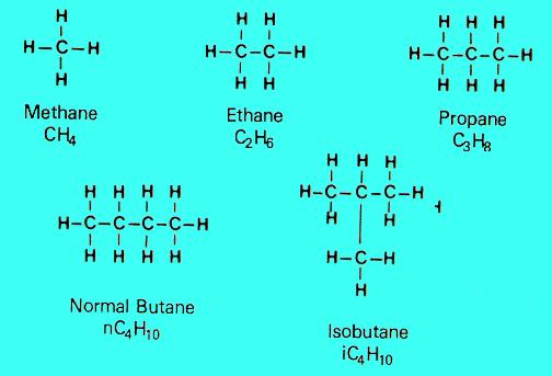
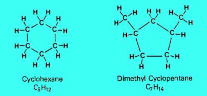
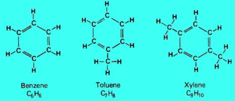
Small quantities of a crude oil may be composed of compounds containing oxygen, nitrogen, sulphur and metals. Sulphur content ranges from traces to more than 5 per cent. If a crude oil contains appreciable quantities of sulphur it is called a sour crude; if it contains little or no sulphur it is called a sweet crude.
The refining process
Every refinery begins with the separation of crude oil into different fractions by distillation.
The fractions are further treated to convert them into mixtures of more useful saleable products by various methods such as cracking, reforming, alkylation, polymerisation and isomerisation. These mixtures of new compounds are then separated using methods such as fractionation and solvent extraction. Impurities are removed by various methods, e.g. dehydration, desalting, sulphur removal and hydrotreating.
Refinery processes have developed in response to changing market demands for certain products. With the advent of the internal combustion engine the main task of refineries became the production of petrol. The quantities of petrol available from distillation alone was insufficient to satisfy consumer demand. Refineries began to look for ways to produce more and better quality petrol. Two types of processes have been developed:
Atmospheric distillation takes place in a distilling column at or near atmospheric pressure. The crude oil is heated to 350 - 400 o C and the vapour and liquid are piped into the distilling column. The liquid falls to the bottom and the vapour rises, passing through a series of perforated trays (sieve trays). Heavier hydrocarbons condense more quickly and settle on lower trays and lighter hydrocarbons remain as a vapour longer and condense on higher trays.
Liquid fractions are drawn from the trays and removed. In this way the light gases, methane, ethane, propane and butane pass out the top of the column, petrol is formed in the top trays, kerosene and gas oils in the middle, and fuel oils at the bottom. Residue drawn of the bottom may be burned as fuel, processed into lubricating oils, waxes and bitumen or used as feedstock for cracking units.
To recover additional heavy distillates from this residue, it may be piped to a second distillation column where the process is repeated under vacuum, called vacuum distillation. This allows heavy hydrocarbons with boiling points of 450 o C and higher to be separated without them partly cracking into unwanted products such as coke and gas.
The heavy distillates recovered by vacuum distillation can be converted into lubricating oils by a variety of processes. The most common of these is called solvent extraction. In one version of this process the heavy distillate is washed with a liquid which does not dissolve in it but which dissolves (and so extracts) the non-lubricating oil components out of it. Another version uses a liquid which does not dissolve in it but which causes the non-lubricating oil components to precipitate (as an extract) from it. Other processes exist which remove impurities by adsorption onto a highly porous solid or which remove any waxes that may be present by causing them to crystallise and precipitate out.

Reforming
Reforming is a process which uses heat, pressure and a catalyst (usually containing platinum) to bring about chemical reactions which upgrade naphthas into high octane petrol and petrochemical feedstock. The naphthas are hydrocarbon mixtures containing many paraffins and naphthenes. In Australia, this naphtha feedstock comes from the crudes oil distillation or catalytic cracking processes, but overseas it also comes from thermal cracking and hydrocracking processes. Reforming converts a portion of these compounds to isoparaffins and aromatics, which are used to blend higher octane petrol.
Cracking
Cracking processes break down heavier hydrocarbon molecules (high boiling point oils) into lighter products such as petrol and diesel. These processes include catalytic cracking, thermal cracking and hydrocracking.
e.g.
A typical reaction:
Catalytic cracking is used to convert heavy hydrocarbon fractions obtained by vacuum distillation into a mixture of more useful products such as petrol and light fuel oil. In this process, the feedstock undergoes a chemical breakdown, under controlled heat ( 450 - 500 o C ) and pressure, in the presence of a catalyst - a substance which promotes the reaction without itself being chemically changed. Small pellets of silica - alumina or silica - magnesia have proved to be the most effective catalysts.
The cracking reaction yields petrol, LPG, unsaturated olefin compounds, cracked gas oils, a liquid residue called cycle oil, light gases and a solid coke residue. Cycle oil is recycled to cause further breakdown and the coke, which forms a layer on the catalyst, is removed by burning. The other products are passed through a fractionator to be separated and separately processed.
Fluid catalytic cracking uses a catalyst in the form of a very fine powder which flows like a liquid when agitated by steam, air or vapour. Feedstock entering the process immediately meets a stream of very hot catalyst and vaporises. The resulting vapours keep the catalyst fluidised as it passes into the reactor, where the cracking takes place and where it is fluidised by the hydrocarbon vapour. The catalyst next passes to a steam stripping section where most of the volatile hydrocarbons are removed. It then passes to a regenerator vessel where it is fluidised by a mixture of air and the products of combustion which are produced as the coke on the catalyst is burnt off. The catalyst then flows back to the reactor. The catalyst thus undergoes a continuous circulation between the reactor, stripper and regenerator sections.
The catalyst is usually a mixture of aluminium oxide and silica. Most recently, the introduction of synthetic zeolite catalysts has allowed much shorter reaction times and improved yields and octane numbers of the cracked gasolines.
Thermal cracking uses heat to break down the residue from vacuum distillation. The lighter elements produced from this process can be made into distillate fuels and petrol. Cracked gases are converted to petrol blending components by alkylation or polymerisation. Naphtha is upgraded to high quality petrol by reforming. Gas oil can be used as diesel fuel or can be converted to petrol by hydrocracking. The heavy residue is converted into residual oil or coke which is used in the manufacture of electrodes, graphite and carbides.
This process is the oldest technology and is not used in Australia.
Hydrocracking can increase the yield of petrol components, as well as being used to produce light distillates. It produces no residues, only light oils. Hydrocracking is catalytic cracking in the presence of hydrogen. The extra hydrogen saturates, or hydrogenates, the chemical bonds of the cracked hydrocarbons and creates isomers with the desired characteristics. Hydrocracking is also a treating process, because the hydrogen combines with contaminants such as sulphur and nitrogen, allowing them to be removed.
Gas oil feed is mixed with hydrogen, heated, and sent to a reactor vessel with a fixed bed catalyst, where cracking and hydrogenation take place. Products are sent to a fractionator to be separated. The hydrogen is recycled. Residue from this reaction is mixed again with hydrogen, reheated, and sent to a second reactor for further cracking under higher temperatures and pressures.
In addition to cracked naphtha for making petrol, hydrocracking yields light gases useful for refinery fuel, or alkylation as well as components for high quality fuel oils, lube oils and petrochemical feedstocks.
Following the cracking processes it is necessary to build or rearrange some of the lighter hydrocarbon molecules into high quality petrol or jet fuel blending components or into petrochemicals. The former can be achieved by several chemical process such as alkylation and isomerisation.
Alkylation
Olefins such as propylene and butylene are produced by catalytic and thermal cracking. Alkylation refers to the chemical bonding of these light molecules with isobutane to form larger branched-chain molecules (isoparaffins) that make high octane petrol.
Olefins and isobutane are mixed with an acid catalyst and cooled. They react to form alkylate, plus some normal butane, isobutane and propane. The resulting liquid is neutralised and separated in a series of distillation columns. Isobutane is recycled as feed and butane and propane sold as liquid petroleum gas (LPG).
e.g.
Isomerisation
Isomerisation refers to chemical rearrangement of straight-chain hydrocarbons (paraffins), so that they contain branches attached to the main chain (isoparaffins). This is done for two reasons:
Polymerisation
Under pressure and temperature, over an acidic catalyst, light unsaturated hydrocarbon molecules react and combine with each other to form larger hydrocarbon molecules. Such process can be used to react butenes (olefin molecules with four carbon atoms) with iso-butane (branched paraffin molecules, or isoparaffins, with four carbon atoms) to obtain a high octane olefinic petrol blending component called polymer gasoline.
Hydrotreating and sulphur plants
A number of contaminants are found in crude oil. As the fractions travel through the refinery processing units, these impurities can damage the equipment, the catalysts and the quality of the products. There are also legal limits on the contents of some impurities, like sulphur, in products.
Hydrotreating is one way of removing many of the contaminants from many of the intermediate or final products. In the hydrotreating process, the entering feedstock is mixed with hydrogen and heated to 300 - 380 o C . The oil combined with the hydrogen then enters a reactor loaded with a catalyst which promotes several reactions:
Air, water and land can all be affected by refinery operations. Refineries are well aware of their responsibility to the community and employ a variety of processes to safeguard the environment.
The processes described below are those used by the Shell refinery at Geelong in Victoria, but all refineries employ similar techniques in managing the environmental aspects of refining.
Air
Preserving air quality around a refinery involves controlling the following emissions:
Smoke is formed when the burning mixture contains insufficient oxygen or is not sufficiently mixed. Modern furnace control systems prevent this from happening during normal operation.
Smells are the most difficult emission to control and the easiest to detect. Refinery smells are generally associated with compounds containing sulphur, where even tiny losses are sufficient to cause a noticeable odour.
Water
Aqueous effluent's consist of cooling water, surface water and process water.
The majority of the water discharged from the refinery has been used for cooling the various process streams. The cooling water does not actually come into contact with the process material and so has very little contamination. The cooling water passes through large "interceptors" which separate any oil from minute leaks etc., prior to discharge. The cooling water system at Geelong Refinery is a once-through system with no recirculation.
Rainwater falling on the refinery site must be treated before discharge to ensure no oily material washed off process equipment leaves the refinery. This is done first by passing the water through smaller "plant oil catchers", which each treat rainwater from separate areas on the site, and then all the streams pass to large "interceptors" similar to those used for cooling water. The rainwater from the production areas is further treated in a Dissolved Air Flotation (DAF) unit. This unit cleans the water by using a flocculation agent to collect any remaining particles or oil droplets and floating the resulting flock to the surface with millions of tiny air bubbles. At the surface the flock is skimmed off and the clean water discharged.
Process water has actually come into contact with the process streams and so can contain significant contamination. This water is treated in the "sour water treater" where the contaminants (mostly ammonia and hydrogen sulphide) are removed and then recovered or destroyed in a downstream plant. The process water, when treated in this way, can be reused in parts of the refinery and discharged through the process area rainwater treatment system and the DAF unit.
Any treated process water that is not reused is discharged as Trade Waste to the sewerage system. This trade waste also includes the effluent from the refinery sewage treatment plant and a portion of treated water from the DAF unit.
As most refineries import and export many feed materials and products by ship, the refinery and harbour authorities are prepared for spillage from the ship or pier. In the event of such a spill, equipment is always on standby at the refinery and it is supported by the facilities of the Australian Marine Oil Spill Centre at Geelong, Victoria.
Land
The refinery safeguards the land environment by ensuring the appropriate disposal of all wastes.
Within the refinery, all hydrocarbon wastes are recycled through the refinery slops system. This system consists of a network of collection pipes and a series of dewatering tanks. The recovered hydrocarbon is reprocessed through the distillation units.
Wastes that cannot be reprocessed are either recycled to manufacturers (e.g. some spent catalysts can be reprocessed), disposed of in EPA-approved facilities off-site, or chemically treated on-site to form inert materials which can be disposed to land-fill within the refinery.
Waste movements within the refinery require a "Process liquid, Sludge and Solid waste disposal permit". Wastes that go off-site must have an EPA "Waste Transport Permit".
http://earthsci.org/mineral/energy/gasexpl/spill.html
Oil Spills
adapted to HTML from Australian Institute of Petroleum with permission
Offshore Exploration Refining Oil Offshore Drilling
Oil spill prevention
Oil spill combat
Combat Techniques
How Dispersants work
The petroleum industry's safety record of handling oil and its products in Australia has been excellent and has been maintained throughout the last two decades of rapidly increasing volumes produced and transported in national waters. Oil spills from offshore production have been insignificant and, while there have been some spills arising from shipping accidents, none has had a lasting adverse impact on the marine environment.
The risks and responsibilities associated with oil in the sea should be put in their true perspective.
Only 14 per cent of the oil in the sea is directly attributable to the world's oil industry. Two per cent of this occurs in spills during the exploration and production phase from rigs and platforms, and 12 per cent is attributable to accidents involving oil tankers.
Another 33 per cent occurs during the operation of vessels other than those used by the oil industry. Usually these are cargo vessels which may be involved in collisions which spill fuel oil or they may discharge waste oil from ballast tanks during a voyage.

Major inputs of petroleum
to the marine environment
Oil spill prevention
Although statistics show that historically the oil industry is directly responsible for only a small proportion of marine oil spills, the oil companies - individually and collectively - do not take the risk of spills lightly. There are strict regulations governing all facets of their operations from the exploration / production phase through to the delivery of refined petroleum products.
Exploration & production: Almost 1,100 wells have been drilled and approximately 3,100 million barrels of oil have been produced in coastal and offshore Australia. Only about 600 barrels have been spilt in the marine environment from exploration and production operations. This is equivalent to the volume contained in a garden swimming pool and taken over a period of 25 years.
Above the water line, special deck drains on each rig and platform collect any waste fluids and channel them into settling tanks where oil is separated out, put into containers and sent to shore for treatment and disposal.
The Australian petroleum industry is a world leader in the treatment of water produced with oil through production wells offshore. Innovative technology includes the use of hydrcyclones and air stripping techniques to ensure the hydrocarbon content of formation water discharged into the sea is well under the Government regulatory limit of 30 parts per million.
The integrity of oil tankers is more difficult to control because the business of tanker operations is complex and fragmented. Oil company-owned vessels make up only about 15 per cent of the world fleet. Oil company-chartered tankers add another 20 per cent.
 Vessels owned and operated by the oil companies in Australia are subject to stringent operating and maintenance requirements. A number of designs have been introduced for new vessels - including double hulls and mid-deck tank designs - to minimise oil loss from tankers in the event of a serious accident at sea.
Oil spill combat
 If, despite all precautions, an oil spill does occur off Australia's coastline, the oil industry in association with government agencies, is well prepared to minimise its impact on the environment.Organisations: Australia has three interconnected oil pollution response organisations - the Australian Marine Oil Spill Centre, the Marine Oil Spills Action Plan, and the National Plan to Combat Pollution of the Sea by Oil.
Australian Marine Oil Spill Centre Ltd (AMOSC): is wholly owned subsidiary of Australian Institute of Petroleum Ltd and is totally managed and funded by the Australian oil industry. There are eleven participating oil companies: Australian Petroleum Pty Limited, BHP Petroleum Pty Ltd, BP Australia Ltd, Esso Australia Ltd, Hadson energy Ltd, Mobil Oil, Australia Ltd, Santos Ltd, The Shell Company of Australia Ltd and Woodside Petroleum Ltd.
The Centre was established in 1990 to provide the equipment and trained personnel required to respond to a major oil spill off Australia's coasts. Based on Corio Bay, near Geelong in Victoria, it houses over $10 million of oil spill combat equipment and materials. This gear and the trained staff are on call 24 hours a day and they can be at the scene of a spill anywhere off Australia's coasts within 12-24 hours of being called out.
If additional back-up is needed AMOSC can call on international aid from a similar organisation based in Singapore (East Asia Response Ltd) as well as the world's largest spill organisation (Oil Spill Service Centre) located in Southampton, England. The latter has its own cargo plane on standby and can be at most locations within 48 hours of receiving a call.
AMOSC also has a purpose-built training centre where regular courses are held in oil response techniques. The Centre trains between 200 and 300 oil industry and government safety personnel each year. Marine Oil Spills Action Plan (MOSAP): was established by the oil industry in 1971 to enable an individual company to obtain assistance from other companies in combating a spill larger than it can handle with its own resources. Like AMOSC, MOSAP is supervised and funded by the oil industry through the Australian Institute of Petroleum.
The industry has provided equipment and clean-up materials at each port around Australia where oil is handled in bulk. A minor spill will be handled by the oil company concerned using the equipment available to it at or near the site. MOSAP is activated if a spill is beyond the capability of the company concerned.
If the spill is of major proportions, contact will be made with AMOSC and the Australian Maritime Safety Authority for assistance.
National Plan to Combat Pollution of the Sea by Oil (NATPLAN) has been in operation since October 1973. It is a combined effort by State and Federal organisations and the oil industry. Oil spill combat equipment is provided at various locations round Australia and a training program is conducted by the Australia Maritime Safety Authority. Funding for NATPLAN is based on the 'polluter pays' principle and a levy is placed on commercial shipping using Australian ports. These funds provide for the maintenance and administration of the Plan and allow for a contingency to cover costs not attributable to the polluter, or which the polluter is unable to meet.
Combat Techniques No two oil spills are the same because of the variation in oil types, locations and weather conditions involved. However, broadly speaking, there are four main methods of response.
Processes Following a Spill
Often the response involves a combination of all these approaches.
Boom types vary from inflatable neoprene tubes to solid, but buoyant material. Most rise up about a metre above the water line. Some are designed to sit flush on tidal flats while others are applicable to deeper water and have skirts which hang down about a metre below the waterline.
Skimmers float across the top of the slick contained within the boom and suck or scoop the oil into storage tanks on nearby vessels or on the shore.
However booms and skimmers are less effective when deployed in high winds and high seas.
Decisions on whether or not to use dispersants to combat an oil spill must be made in each individual case. The decision will take into account the time since the spill, the weather conditions, the particular environment involved and the type of oil that has been spilt.

Bioremediation: Most of the components of oil washed up along a shoreline;can be broken down by bacteria and other micro-organisms into harmless substances such as fatty acids and carbon dioxide. This action is called bio-degradation. The addition of fertilising nutrients like nitrogen and phosphorous which stimulate growth of the micro-organisms concerned.
However the effectiveness of this technique depends on factors such as whether the ground treated has sand or pebbles and whether the fertiliser is water soluble or applied in pellet or liquid form.

The Basic Terms
The Origin of Oil and Gas
Conditions for Oil and Gas Formation
Occurrence of Oil and Gas - four conditions
Types of Oil Traps
oil dome photo
oil dome section
fault trap
sand lens
salt dome
unconformity trap
see also Oil Deposits - types of traps (different file)
see also Bio Fuels Fuels Oil and Gas Exploration Offshore Oil and Gas Refining Oil Spills
The Basic Terms
Petroleum
- A broad term which includes both crude oil and natural gas
Crude Oil
- a liquid mixture of naturally occurring hydrocarbons (compounds containing carbon and oxygen).
Natural Gas
- A gaseous mixture of naturally occurring hydrocarbons.
The Origin of Oil and Gas
Oil and natural gas originate from organic matter in marine sediment. Microscopic organisms such as single-celled algae settle to the sea floor and accumulate in marine mud. This organic matter may partially decompose, using up the dissolved oxygen in the sediment. As soon as the oxygen is used up, decay stops and the remaining organic matter is preserved. Continued burial subjects the organic matter to higher temperatures and pressures, which cause physical and chemical changes in the organic compounds. These changes produce tiny droplets of oil and natural gas. As muddy sediments compact, the oil and gas are squeezed out and move into more porous and permeable sandy layers.
Conditions for Oil and Gas Formation
Anaerobic
- conditions under which oxygen is not present. This is the condition necessary for the formation of oil and gas. Such conditions are found in a highly restrictive environment such as in a closed basin like the bottom of the Black Sea.
Aerobic
- conditions under which oxygen is present to oxidize organic material and sulfur.
Occurrence of Oil and Gas
Four conditions or requirements are necessary in order for large accumulations of oil and gas to form. The requirements are:
Source Rock
- A shale must contain organic material which has not been oxidized and which is converted to petroleum by burial pressures and temperatures.
Reservoir Rock
- A sandstone or other relatively porous rock is required to store and transmit the petroleum when wells are drilled into the reservoir.
A Trap
- a set of conditions to hold the petroleum in a reservoir and prevent its escape by migration.
Deep enough burial but not too deep - Temperatures and Pressures are required to "cook" the petroleum out of the organic matter. Of course, if the rock gets too hot the petroleum is all "burned" off.
Types of traps:
Oil Dome
Oil Dome in section
Fault Trap
Sand Lens
Salt Dome
Unconformity Trap
http://earthsci.org/mineral/energy/gasexpl/offshore.html
Offshore Oil Drilling
adapted to HTML from Australian Institute of Petroleum with permission Offshore Exploration Oil Spills Refining Oil
Drilling or digging for oil has occurred in one way or another for hundreds of years. The Chinese, for instance, invented a bamboo rig to obtain oil and gas for lighting and cooking.
But only in the last 40 years has humankind been able to efficiently extract petroleum from beneath the seas - an achievement to rank with this century's mightiest technological triumphs. In Australia, nearly 90 per cent of our petroleum wealth is found offshore. The search is difficult, extremely expensive, and often fruitless - but critical to the nation's economic future.
Locating an oil and gas "trap" - as it is known - and extracting the oil and gas is difficult enough on land. But offshore, in deep and often stormy waters, it becomes an awesome undertaking.
Potential traps are identified by analysing seismic survey data but whether they contain oil or gas won't be known until a drill bit penetrates the structure. Directing the drill bit to a precise location - perhaps several kilometres away - requires sophisticated computer technology. A navigation device installed above the drill bit feeds back information which enables the exact position of the well to be measured and monitored. A steerable motor within the drillpipe can be remotely controlled to adjust the direction of the drill.
 | 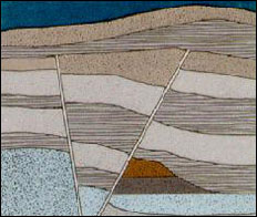 | |
| Anticlinal Trap | Fault Trap |
Environmental safeguards
The Australian offshore petroleum industry has always contended that its activities are environmentally friendly.
The industry's case has now been given increased strength with the findings of the Independent Scientific Review Committee (ISRC) inquiry commissioned by the Australian Petroleum Exploration Association.
In Australia up to 100 offshore wells per year are drilled. About a quarter of these are development wells to produce oil or gas found by previous drilling.
Before a well can be drilled, government approval must be obtained. Drilling must then conform to statutory conditions and further operations are covered by industry Codes of Practice.
The Independent Scientific Review has found that environmental impacts from offshore exploration and production are negligible. The ISR examined the potential environmental effects of discharge of drilling fluids, drill cuttings and "produced formation water" (PFW).
Companies in Australia safeguard the environment and minimise impacts in a number of ways.
Drilling fluids used in Australia are almost exclusively water-based, not oil-based.
During production, oil is separated from the water by mechanical devices before the produced formation water is returned to sea. Australia's regulations on how much petroleum hydrocarbon is contained in PFW are among the world's strictest.
Sophisticated and reliable blowout prevention systems (BOP) are used in every production well to minimise the possibility of a blowout - where uncontrolled fluids flow from a well.
Four drilling rig types
In the early days of offshore drilling, explorers simply fitted a derrick to a barge and towed it to their site. Today, four types of offshore rigs are used to drill wildcat or exploration wells.
Submersibles. These are rarely used. They can be floated to shallow water locations then ballasted to sit on the seabed. Jackups. Usually towed to a location. Their legs are then lowered to the seabed and the hull is jacked-up clear of the sea surface. Used in waters to about 160 metres deep.Production platforms Once oil or gas is discovered, the drilling rig is generally replaced by a production platform, assembled at the site using a barge equipped with heavy lift cranes.
Drill ship. These look like ordinary ships but have a derrick on top which drills through a hole in the hull. Drill ships are either anchored or positioned with computer-controlled propellers along the hull which continually correct the ships drift. Often used to drill "wildcat" wells in deep waters.
Semi submersible. Mobile structures, some with their own locomotion. Their superstructures are supported by columns sitting on hulls or pontoons which are ballasted below the water surface. They provide excellent stability in rough, deep seas.
Platforms vary in size, shape and type depending on the size of the field, the water depth and the distance from shore. In Australia's medium to large fields, fixed production platforms are commonly used.
These are made of steel and fixed to the seabed with steel piles. These platforms house all the processing equipment and accommodate up to 80 workers who typically work a 12 hour day, one week on and one week off. There are also concrete structures which are big enough to store oil. Gravity holds them on the seabed.
The world's biggest platforms are bigger than a football field and rise above the water as high as a 25 storey office tower. They are home to 500 workers.
If the field is in shallow water and near land or another platform, small remotely controlled monopod platforms may be used. Another system is a floating structure, either anchored or tethered, called a Floating Production Storage Offloading (FPSO) vessel.
Another platform type, suitable for deep water production, is the Tension Leg platform, built of steel or concrete and anchored to the sea floor with vertical "tendons".
Drilling for oil
The first stage of drilling is called "spudding" and drilling starts when the drill bit is lowered into the seabed.
The bit can be of two types: - a roller cone or rock bit which usually has three cones armed with steel or tungsten carbide : teeth:; or buttons; or - a diamond bit, imbedded with small industrial diamonds.
The drill bit is attached to drill pipe (or a drill string) and rotated by a turntable on the platform floor. As the hole deepens, extra lengths of drill pipe are attached.
A length of drill pipe is 30 feet long, or 9.1 metres (oil workers use the old imperial measurement system). The drill bit ranges in diameter from 36 inches or approximately 91.4 centimetres (used at the start of the hole) to eight and a half inches (approximately 21.5 centimetres).
Drilling may take weeks or months before the targeted location is reached.
The major potential environmental effects from offshore drilling result from the discharge of wastes, including drilling fluids, drill cuttings and "produced formation water" (PFW).
Drilling fluid
Drilling fluid is pumped down the drill pipe and into the hole at high velocity through nozzles in the drill bit. The fluid is usually a mixture of water, clay, a weighting material (usually barite), and various chemicals.
The drilling fluid serves several purposes. It raises the drill cutting to the surface for disposal; it provides the "weight" to keep the underground pressures in check; it keeps the hold stable by caking the wall with a thin layer of clay; and it cleans and cools the bit.
The fluid is recycled through a circulation system where equipment mounted on the drilling rig separates out the drill cuttings and allows the clean fluid to be pumped back down the hole. With few exceptions, Australian wells since 1985 have been drilled using water-based drilling fluids, not oil-based.
The ISRC concluded that "drilling waste discharges have generally been shown to have only minor effects on water quality and pelagic ecosystems".
Evidence collected by the ISRC suggests that acute toxic effects of drilling fluids on marine organisms are only found at very high concentrations. "Toxic effects on the biota in the water column from such concentrations would only be present within a few tens of metres from the point of discharge and only for short times after discharge".
As the plume of drilling fluid and cuttings falls to the seabed, it disperses, with 90 percent of it settling within 100 metres of the platform. Soluble waste concentrations will have fallen by a factor of 10,000 within 100 metres and suspended sediment concentrations by a factor of at least 50,000.
Drill cuttings
As the well is drilled, the "cuttings", consisted of crushed rock and clay, are brought to the surface by the drilling fluid and discharged overboard.
New measures to reduce discharges such as re-injecting the cuttings into the well and slim hole drilling are being examined and tested by the industry.
Produced formation water
Where you find oil, you often also find water. As oil is drawn from a reservoir, it is therefore necessary to separate the water and return it to the ocean.
This is what is known as "produced formation water" (PFW). Great emphasis is placed on ensuring that the water returned to the ocean is as free as possible from oil and chemicals. Strict regulations apply on how much petroleum hydrocarbon is contained in PFW. The Australian regulatory limit is 30 mg/litre average. Mechanical separation devices and chemical treatments are used to separate oil and water efficiently.
Preventing "blow-outs"
The weight of the drilling fluid acts as the first line of well control by keeping underground pressures in check. If an influx of pressurised oil or gas does occur during drilling, well control is maintained through the rig's blowout prevention system (BOP). This is a set of hydraulically operated valves and other closure devices (rams) which seal off the well, and route the wellbore fluids to specialised pressure controlling equipment.
Trained personnel operating this highly reliable equipment minimise the possibility of a "blowout", or an uncontrolled flow of fluids from a well.
Directional drilling
Drilling an oil well may not be a case of going straight down. Directional drilling has been developed where drill bits are steered laterally over a distance of up to several kilometres towards the petroleum reservoir.
One production platform is often used to drill a number of wells, in a variety of directions and inclinations. To steer the drill bit, a downhole motor may be used. It is turned by pumping the drilling mud through it.
Completing the well
When the well has been drilled to its target depth, production casing is set and cemented.
Tubing is lowered into the hole together with "packers" which seal the space between the tubing and the casing. Finally, at the end of the well, the casing is perforated at predetermined depths by small explosive charges detonated remotely. The small holes in the casing allow the oil or gas under its natural pressure to flow to the surface.
A dry well
If the drilled hole is considered to be "dry" or not worth developing, the decision is made to "plug and abandon" it. This involves setting several cement plugs in the well.
Refining of Petroleum
adapted to HTML from Australian Institute of Petroleum with permission Offshore Exploration Offshore Drilling Oil Spills
Petroleum is a complex mixture of organic liquids called crude oil and natural gas, which occurs naturally in the ground and was formed millions of years ago. Crude oil varies from oilfield to oilfield in colour and composition, from a pale yellow low viscosity liquid to heavy black 'treacle' consistencies. Crude oil and natural gas are extracted from the ground, on land or under the oceans, by sinking an oil well and are then transported by pipeline and/or ship to refineries where their components are processed into refined products. Crude oil and natural gas are of little use in their raw state; their value lies in what is created from them: fuels, lubricating oils, waxes, asphalt, petrochemicals and pipeline quality natural gas. An oil refinery is an organised and coordinated arrangement of manufacturing processes designed to produce physical and chemical changes in crude oil to convert it into everyday products like petrol, diesel, lubricating oil, fuel oil and bitumen.
As crude oil comes from the well it contains a mixture of hydrocarbon compounds and relatively small quantities of other materials such as oxygen, nitrogen, sulphur, salt and water. In the refinery, most of these non - hydrocarbon substances are removed and the oil is broken down into its various components, and blended into useful products.
Natural gas from the well, while principally methane, contains quantities of other hydrocarbons - ethane, propane, butane, pentane and also carbon dioxide and water. These components are separated from the methane at a gas fractionation plant.
Petroleum hydrocarbon structures
Petroleum consists of three main hydrocarbon groups:
Paraffins
- These consist of straight or branched carbon rings saturated with hydrogen atoms, the simplest of which is methane ( CH 4) the main ingredient of natural gas. Others in this group include ethane ( C 2 H 6), and propane ( C 3 H 8).
- With very few carbon atoms ( C 1to C 4) are light in density and are gases under normal atmospheric pressure. Chemically paraffins are very stable compounds.
- Naphthenes consist of carbon rings, sometimes with side chains, saturated with hydrogen atoms. Naphthenes are chemically stable, they occur naturally in crude oil and have properties similar to paraffins.
- aromatic hydrocarbons are compounds that contain a ring of six carbon atoms with alternating double and single bonds and six attached hydrogen atoms. This type of structure is known as a benzene ring. They occur naturally in crude oil, and can also be created by the refining process.
Small quantities of a crude oil may be composed of compounds containing oxygen, nitrogen, sulphur and metals. Sulphur content ranges from traces to more than 5 per cent. If a crude oil contains appreciable quantities of sulphur it is called a sour crude; if it contains little or no sulphur it is called a sweet crude.
The refining process
Every refinery begins with the separation of crude oil into different fractions by distillation.
The fractions are further treated to convert them into mixtures of more useful saleable products by various methods such as cracking, reforming, alkylation, polymerisation and isomerisation. These mixtures of new compounds are then separated using methods such as fractionation and solvent extraction. Impurities are removed by various methods, e.g. dehydration, desalting, sulphur removal and hydrotreating.
Refinery processes have developed in response to changing market demands for certain products. With the advent of the internal combustion engine the main task of refineries became the production of petrol. The quantities of petrol available from distillation alone was insufficient to satisfy consumer demand. Refineries began to look for ways to produce more and better quality petrol. Two types of processes have been developed:
- breaking down large, heavy hydrocarbon molecules
- reshaping or rebuilding hydrocarbon molecules.
Atmospheric distillation takes place in a distilling column at or near atmospheric pressure. The crude oil is heated to 350 - 400 o C and the vapour and liquid are piped into the distilling column. The liquid falls to the bottom and the vapour rises, passing through a series of perforated trays (sieve trays). Heavier hydrocarbons condense more quickly and settle on lower trays and lighter hydrocarbons remain as a vapour longer and condense on higher trays.
Liquid fractions are drawn from the trays and removed. In this way the light gases, methane, ethane, propane and butane pass out the top of the column, petrol is formed in the top trays, kerosene and gas oils in the middle, and fuel oils at the bottom. Residue drawn of the bottom may be burned as fuel, processed into lubricating oils, waxes and bitumen or used as feedstock for cracking units.
To recover additional heavy distillates from this residue, it may be piped to a second distillation column where the process is repeated under vacuum, called vacuum distillation. This allows heavy hydrocarbons with boiling points of 450 o C and higher to be separated without them partly cracking into unwanted products such as coke and gas.
The heavy distillates recovered by vacuum distillation can be converted into lubricating oils by a variety of processes. The most common of these is called solvent extraction. In one version of this process the heavy distillate is washed with a liquid which does not dissolve in it but which dissolves (and so extracts) the non-lubricating oil components out of it. Another version uses a liquid which does not dissolve in it but which causes the non-lubricating oil components to precipitate (as an extract) from it. Other processes exist which remove impurities by adsorption onto a highly porous solid or which remove any waxes that may be present by causing them to crystallise and precipitate out.
Reforming
Reforming is a process which uses heat, pressure and a catalyst (usually containing platinum) to bring about chemical reactions which upgrade naphthas into high octane petrol and petrochemical feedstock. The naphthas are hydrocarbon mixtures containing many paraffins and naphthenes. In Australia, this naphtha feedstock comes from the crudes oil distillation or catalytic cracking processes, but overseas it also comes from thermal cracking and hydrocracking processes. Reforming converts a portion of these compounds to isoparaffins and aromatics, which are used to blend higher octane petrol.
- paraffins are converted to isoparaffins
- paraffins are converted to naphthenes
- naphthenes are converted to aromatics
| catalyst | ||||||
|---|---|---|---|---|---|---|
| heptane | -> | toluene | + | hydrogen | ||
| C 7 H 16 | -> | C 7 H 8 | + | 4H 2 |
| catalyst | ||||||
|---|---|---|---|---|---|---|
| cyclohexane | -> | benzene | + | hydrogen | ||
| C 6 H 12 | -> | C 6 H 6 | + | 3H 2 |
Cracking processes break down heavier hydrocarbon molecules (high boiling point oils) into lighter products such as petrol and diesel. These processes include catalytic cracking, thermal cracking and hydrocracking.
e.g.
A typical reaction:
| catalyst | ||||||
|---|---|---|---|---|---|---|
| C 16 H 34 | -> | C 8 H 18 | + | C 8 H 16 |
Catalytic cracking is used to convert heavy hydrocarbon fractions obtained by vacuum distillation into a mixture of more useful products such as petrol and light fuel oil. In this process, the feedstock undergoes a chemical breakdown, under controlled heat ( 450 - 500 o C ) and pressure, in the presence of a catalyst - a substance which promotes the reaction without itself being chemically changed. Small pellets of silica - alumina or silica - magnesia have proved to be the most effective catalysts.
The cracking reaction yields petrol, LPG, unsaturated olefin compounds, cracked gas oils, a liquid residue called cycle oil, light gases and a solid coke residue. Cycle oil is recycled to cause further breakdown and the coke, which forms a layer on the catalyst, is removed by burning. The other products are passed through a fractionator to be separated and separately processed.
Fluid catalytic cracking uses a catalyst in the form of a very fine powder which flows like a liquid when agitated by steam, air or vapour. Feedstock entering the process immediately meets a stream of very hot catalyst and vaporises. The resulting vapours keep the catalyst fluidised as it passes into the reactor, where the cracking takes place and where it is fluidised by the hydrocarbon vapour. The catalyst next passes to a steam stripping section where most of the volatile hydrocarbons are removed. It then passes to a regenerator vessel where it is fluidised by a mixture of air and the products of combustion which are produced as the coke on the catalyst is burnt off. The catalyst then flows back to the reactor. The catalyst thus undergoes a continuous circulation between the reactor, stripper and regenerator sections.
The catalyst is usually a mixture of aluminium oxide and silica. Most recently, the introduction of synthetic zeolite catalysts has allowed much shorter reaction times and improved yields and octane numbers of the cracked gasolines.
Thermal cracking uses heat to break down the residue from vacuum distillation. The lighter elements produced from this process can be made into distillate fuels and petrol. Cracked gases are converted to petrol blending components by alkylation or polymerisation. Naphtha is upgraded to high quality petrol by reforming. Gas oil can be used as diesel fuel or can be converted to petrol by hydrocracking. The heavy residue is converted into residual oil or coke which is used in the manufacture of electrodes, graphite and carbides.
This process is the oldest technology and is not used in Australia.
Hydrocracking can increase the yield of petrol components, as well as being used to produce light distillates. It produces no residues, only light oils. Hydrocracking is catalytic cracking in the presence of hydrogen. The extra hydrogen saturates, or hydrogenates, the chemical bonds of the cracked hydrocarbons and creates isomers with the desired characteristics. Hydrocracking is also a treating process, because the hydrogen combines with contaminants such as sulphur and nitrogen, allowing them to be removed.
Gas oil feed is mixed with hydrogen, heated, and sent to a reactor vessel with a fixed bed catalyst, where cracking and hydrogenation take place. Products are sent to a fractionator to be separated. The hydrogen is recycled. Residue from this reaction is mixed again with hydrogen, reheated, and sent to a second reactor for further cracking under higher temperatures and pressures.
In addition to cracked naphtha for making petrol, hydrocracking yields light gases useful for refinery fuel, or alkylation as well as components for high quality fuel oils, lube oils and petrochemical feedstocks.
Following the cracking processes it is necessary to build or rearrange some of the lighter hydrocarbon molecules into high quality petrol or jet fuel blending components or into petrochemicals. The former can be achieved by several chemical process such as alkylation and isomerisation.
Alkylation
Olefins such as propylene and butylene are produced by catalytic and thermal cracking. Alkylation refers to the chemical bonding of these light molecules with isobutane to form larger branched-chain molecules (isoparaffins) that make high octane petrol.
Olefins and isobutane are mixed with an acid catalyst and cooled. They react to form alkylate, plus some normal butane, isobutane and propane. The resulting liquid is neutralised and separated in a series of distillation columns. Isobutane is recycled as feed and butane and propane sold as liquid petroleum gas (LPG).
e.g.
| catalyst | ||||||
|---|---|---|---|---|---|---|
| isobutane | + | butylene | -> | isooctane | ||
| C 4 H 10 | + | C 4 H 8 | -> | C 8 H 18 |
Isomerisation
Isomerisation refers to chemical rearrangement of straight-chain hydrocarbons (paraffins), so that they contain branches attached to the main chain (isoparaffins). This is done for two reasons:
- they create extra isobutane feed for alkylation
- they improve the octane of straight run pentanes and hexanes and hence make them into better petrol blending components.
Polymerisation
Under pressure and temperature, over an acidic catalyst, light unsaturated hydrocarbon molecules react and combine with each other to form larger hydrocarbon molecules. Such process can be used to react butenes (olefin molecules with four carbon atoms) with iso-butane (branched paraffin molecules, or isoparaffins, with four carbon atoms) to obtain a high octane olefinic petrol blending component called polymer gasoline.
Hydrotreating and sulphur plants
A number of contaminants are found in crude oil. As the fractions travel through the refinery processing units, these impurities can damage the equipment, the catalysts and the quality of the products. There are also legal limits on the contents of some impurities, like sulphur, in products.
Hydrotreating is one way of removing many of the contaminants from many of the intermediate or final products. In the hydrotreating process, the entering feedstock is mixed with hydrogen and heated to 300 - 380 o C . The oil combined with the hydrogen then enters a reactor loaded with a catalyst which promotes several reactions:
- hydrogen combines with sulphur to form hydrogen sulphide ( H 2 S )
- nitrogen compounds are converted to ammonia
- any metals contained in the oil are deposited on the catalyst
- some of the olefins, aromatics or naphthenes become saturated with hydrogen to become paraffins and some cracking takes place, causing the creation of some methane, ethane, propane and butanes.
- the removal of the hydrogen sulphide gas from the hydrocarbon stream
- the conversion of hydrogen sulphide to elemental sulphur, a non-toxic and useful chemical.
- Combustion of part of the H 2 S stream in a furnace, producing sulphur dioxide ( SO 2) water ( H 2 O ) and sulphur (S).
- Reaction of the remainder of the H 2 S with the combustion products in the presence of a catalyst. The H 2 S reacts with the SO 2to form sulphur.
| 2H 2 S | + | 2O 2 | -> | SO 2 | + | S | + | 2H 2 O |
| 2H 2 S | + | 2O 2 | -> | 3S | + | 2H 2 O |
Air, water and land can all be affected by refinery operations. Refineries are well aware of their responsibility to the community and employ a variety of processes to safeguard the environment.
The processes described below are those used by the Shell refinery at Geelong in Victoria, but all refineries employ similar techniques in managing the environmental aspects of refining.
Air
Preserving air quality around a refinery involves controlling the following emissions:
- sulphur oxides
- hydrocarbon vapours
- smoke
- smells
Smoke is formed when the burning mixture contains insufficient oxygen or is not sufficiently mixed. Modern furnace control systems prevent this from happening during normal operation.
Smells are the most difficult emission to control and the easiest to detect. Refinery smells are generally associated with compounds containing sulphur, where even tiny losses are sufficient to cause a noticeable odour.
Water
Aqueous effluent's consist of cooling water, surface water and process water.
The majority of the water discharged from the refinery has been used for cooling the various process streams. The cooling water does not actually come into contact with the process material and so has very little contamination. The cooling water passes through large "interceptors" which separate any oil from minute leaks etc., prior to discharge. The cooling water system at Geelong Refinery is a once-through system with no recirculation.
Rainwater falling on the refinery site must be treated before discharge to ensure no oily material washed off process equipment leaves the refinery. This is done first by passing the water through smaller "plant oil catchers", which each treat rainwater from separate areas on the site, and then all the streams pass to large "interceptors" similar to those used for cooling water. The rainwater from the production areas is further treated in a Dissolved Air Flotation (DAF) unit. This unit cleans the water by using a flocculation agent to collect any remaining particles or oil droplets and floating the resulting flock to the surface with millions of tiny air bubbles. At the surface the flock is skimmed off and the clean water discharged.
Process water has actually come into contact with the process streams and so can contain significant contamination. This water is treated in the "sour water treater" where the contaminants (mostly ammonia and hydrogen sulphide) are removed and then recovered or destroyed in a downstream plant. The process water, when treated in this way, can be reused in parts of the refinery and discharged through the process area rainwater treatment system and the DAF unit.
Any treated process water that is not reused is discharged as Trade Waste to the sewerage system. This trade waste also includes the effluent from the refinery sewage treatment plant and a portion of treated water from the DAF unit.
As most refineries import and export many feed materials and products by ship, the refinery and harbour authorities are prepared for spillage from the ship or pier. In the event of such a spill, equipment is always on standby at the refinery and it is supported by the facilities of the Australian Marine Oil Spill Centre at Geelong, Victoria.
Land
The refinery safeguards the land environment by ensuring the appropriate disposal of all wastes.
Within the refinery, all hydrocarbon wastes are recycled through the refinery slops system. This system consists of a network of collection pipes and a series of dewatering tanks. The recovered hydrocarbon is reprocessed through the distillation units.
Wastes that cannot be reprocessed are either recycled to manufacturers (e.g. some spent catalysts can be reprocessed), disposed of in EPA-approved facilities off-site, or chemically treated on-site to form inert materials which can be disposed to land-fill within the refinery.
Waste movements within the refinery require a "Process liquid, Sludge and Solid waste disposal permit". Wastes that go off-site must have an EPA "Waste Transport Permit".
http://earthsci.org/mineral/energy/gasexpl/spill.html
Oil Spills
adapted to HTML from Australian Institute of Petroleum with permission Offshore Exploration Refining Oil Offshore Drilling
Oil spill prevention
Oil spill combat
Combat Techniques
How Dispersants work
The petroleum industry's safety record of handling oil and its products in Australia has been excellent and has been maintained throughout the last two decades of rapidly increasing volumes produced and transported in national waters. Oil spills from offshore production have been insignificant and, while there have been some spills arising from shipping accidents, none has had a lasting adverse impact on the marine environment.
The risks and responsibilities associated with oil in the sea should be put in their true perspective.
Only 14 per cent of the oil in the sea is directly attributable to the world's oil industry. Two per cent of this occurs in spills during the exploration and production phase from rigs and platforms, and 12 per cent is attributable to accidents involving oil tankers.
Another 33 per cent occurs during the operation of vessels other than those used by the oil industry. Usually these are cargo vessels which may be involved in collisions which spill fuel oil or they may discharge waste oil from ballast tanks during a voyage.
Major inputs of petroleum
to the marine environment
Oil spill prevention
Although statistics show that historically the oil industry is directly responsible for only a small proportion of marine oil spills, the oil companies - individually and collectively - do not take the risk of spills lightly. There are strict regulations governing all facets of their operations from the exploration / production phase through to the delivery of refined petroleum products.
Exploration & production: Almost 1,100 wells have been drilled and approximately 3,100 million barrels of oil have been produced in coastal and offshore Australia. Only about 600 barrels have been spilt in the marine environment from exploration and production operations. This is equivalent to the volume contained in a garden swimming pool and taken over a period of 25 years.
Above the water line, special deck drains on each rig and platform collect any waste fluids and channel them into settling tanks where oil is separated out, put into containers and sent to shore for treatment and disposal.
The Australian petroleum industry is a world leader in the treatment of water produced with oil through production wells offshore. Innovative technology includes the use of hydrcyclones and air stripping techniques to ensure the hydrocarbon content of formation water discharged into the sea is well under the Government regulatory limit of 30 parts per million.
The integrity of oil tankers is more difficult to control because the business of tanker operations is complex and fragmented. Oil company-owned vessels make up only about 15 per cent of the world fleet. Oil company-chartered tankers add another 20 per cent.
Vessels owned and operated by the oil companies in Australia are subject to stringent operating and maintenance requirements. A number of designs have been introduced for new vessels - including double hulls and mid-deck tank designs - to minimise oil loss from tankers in the event of a serious accident at sea. Oil spill combat
If, despite all precautions, an oil spill does occur off Australia's coastline, the oil industry in association with government agencies, is well prepared to minimise its impact on the environment.Organisations: Australia has three interconnected oil pollution response organisations - the Australian Marine Oil Spill Centre, the Marine Oil Spills Action Plan, and the National Plan to Combat Pollution of the Sea by Oil. Australian Marine Oil Spill Centre Ltd (AMOSC): is wholly owned subsidiary of Australian Institute of Petroleum Ltd and is totally managed and funded by the Australian oil industry. There are eleven participating oil companies: Australian Petroleum Pty Limited, BHP Petroleum Pty Ltd, BP Australia Ltd, Esso Australia Ltd, Hadson energy Ltd, Mobil Oil, Australia Ltd, Santos Ltd, The Shell Company of Australia Ltd and Woodside Petroleum Ltd.
The Centre was established in 1990 to provide the equipment and trained personnel required to respond to a major oil spill off Australia's coasts. Based on Corio Bay, near Geelong in Victoria, it houses over $10 million of oil spill combat equipment and materials. This gear and the trained staff are on call 24 hours a day and they can be at the scene of a spill anywhere off Australia's coasts within 12-24 hours of being called out.
If additional back-up is needed AMOSC can call on international aid from a similar organisation based in Singapore (East Asia Response Ltd) as well as the world's largest spill organisation (Oil Spill Service Centre) located in Southampton, England. The latter has its own cargo plane on standby and can be at most locations within 48 hours of receiving a call.
AMOSC also has a purpose-built training centre where regular courses are held in oil response techniques. The Centre trains between 200 and 300 oil industry and government safety personnel each year. Marine Oil Spills Action Plan (MOSAP): was established by the oil industry in 1971 to enable an individual company to obtain assistance from other companies in combating a spill larger than it can handle with its own resources. Like AMOSC, MOSAP is supervised and funded by the oil industry through the Australian Institute of Petroleum.
The industry has provided equipment and clean-up materials at each port around Australia where oil is handled in bulk. A minor spill will be handled by the oil company concerned using the equipment available to it at or near the site. MOSAP is activated if a spill is beyond the capability of the company concerned.
If the spill is of major proportions, contact will be made with AMOSC and the Australian Maritime Safety Authority for assistance.
National Plan to Combat Pollution of the Sea by Oil (NATPLAN) has been in operation since October 1973. It is a combined effort by State and Federal organisations and the oil industry. Oil spill combat equipment is provided at various locations round Australia and a training program is conducted by the Australia Maritime Safety Authority. Funding for NATPLAN is based on the 'polluter pays' principle and a levy is placed on commercial shipping using Australian ports. These funds provide for the maintenance and administration of the Plan and allow for a contingency to cover costs not attributable to the polluter, or which the polluter is unable to meet.
Combat Techniques No two oil spills are the same because of the variation in oil types, locations and weather conditions involved. However, broadly speaking, there are four main methods of response.
- Leave the oil alone so that it breaks down by natural means.
- Contain the spill with booms and collect it from the water surface using skimmer equipment.
- Use dispersants to break up the oil and speed its natural biodegradation.
- Introduce biological agents to the spill to hasten biodegradation.
Processes Following a Spill
Often the response involves a combination of all these approaches.
Boom types vary from inflatable neoprene tubes to solid, but buoyant material. Most rise up about a metre above the water line. Some are designed to sit flush on tidal flats while others are applicable to deeper water and have skirts which hang down about a metre below the waterline.
Skimmers float across the top of the slick contained within the boom and suck or scoop the oil into storage tanks on nearby vessels or on the shore.
However booms and skimmers are less effective when deployed in high winds and high seas.
Decisions on whether or not to use dispersants to combat an oil spill must be made in each individual case. The decision will take into account the time since the spill, the weather conditions, the particular environment involved and the type of oil that has been spilt.
Bioremediation: Most of the components of oil washed up along a shoreline;can be broken down by bacteria and other micro-organisms into harmless substances such as fatty acids and carbon dioxide. This action is called bio-degradation. The addition of fertilising nutrients like nitrogen and phosphorous which stimulate growth of the micro-organisms concerned.
However the effectiveness of this technique depends on factors such as whether the ground treated has sand or pebbles and whether the fertiliser is water soluble or applied in pellet or liquid form.
Powered by  Translate
Translate
Subscribe to:
Posts (Atom)